Volume 5, Number 4 - April
2000
Journal of the Home Metal Shop
Club of Houston
Notes from the President
By: Keith Mitchell
I would like some feedback on the FIRST Robotics competition. What went
well. What could be improved. I understand we had a pretty light turnout.
In the February meeting we talked about how to address remote members.
There were diverse opinions and no resolution. In the April Business meeting
I would like to appoint a study committee to collect the issues regarding
remote members.
Also in the April business meeting I would like to appoint a nominating
committee for the new officers election in June. In prior years we have
appointed the committee in May and had the election in June. Some of the
candidates got ambushed. They didn't know until the election they had been
nominated and were not prepared to serve.
In this newsletter, is a new feature I thought we would give a try.
When the club was first formed part of the meeting protocol was for everyone
to introduce themselves. In this manner we began to know something about
each other and better define what we had in common. Members learned they
shared the same machinery or interest which stimulated exchange of ideas.
As we have grown that process has become too cumbersome and time consuming
to work with a larger group. To restore the benefits of this without spending
a lot of everyone's time I thought we would try to profile one member in
each newsletter. This information will go only in the mail out newsletter,
not to the website. Since John Korman is one of the club founders I felt
it was fitting that he be first.
Finally, Gordon Lawson is responsible for maintaining our member list.
I've sent out several e-mails to everyone recently. If you have not been
receiving the e-mail or newsletter we probably don't have an accurate address.
If you would like to be included please update your information with Gordon
at Gordon.lawson@uk.akzonobel.com
April Business Meeting Agenda
1. Treasury Balance
2. Appoint Study Committee for Remote Members
3. Appoint Officer Nominating Committee
March Meeting Minutes
1. No business meeting was held in March
1. Chips Meeting - The March meeting was held in conjunction with the
FIRST Robotics competition. No formal notes were taken.
Foundry Group Notes
By Keith Mitchell
We have the Petrobond kit from budget Casting Supply. By April 22 we
will have obtained and mulled the sand. The remaining ingredient will be
some aluminum scrap and safety equipment. For everyone attending the April
22 pour the minimum safety equipment will be long pants, a long sleeve
shirt, face shield, and safety glasses. If you are planning on handling
any of the aluminum crucibles long gauntlet welding gloves are also required.
If you have patterns to mold and pour, you will also need a suitably sized
molding flask. We will have 100# of Petrobond. The objective of this exercise
is to melt some scrap to refine to ingots for future use and to test pour
a few molds. For an update of the April 22 pour click
here
Grinder Pedestal
By Keith Mitchell
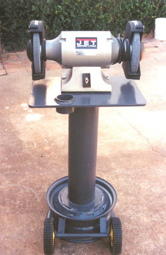 The photo at
left is of a pedestal I build for my bench grinders. I was looking for
several features in the grinder base. First I was looking for a stable
base which would help with any vibration dampening. Second I was looking
for some level of portability. This base design meets these criteria.
The photo at
left is of a pedestal I build for my bench grinders. I was looking for
several features in the grinder base. First I was looking for a stable
base which would help with any vibration dampening. Second I was looking
for some level of portability. This base design meets these criteria.
This is primarily a welding project. The pedestal is made from an auto
tire rim, pipe, and plate. The base and pedestal are filled with concrete
to provide additional weight and vibration dampening. Wheels are provided
to allow easy movement. I obtain my tire rims from multiple sources. Since
it's not important that they be round or serviceable they are cheap, $5-7.
The column for the base shown is made from 6-5/8" pipe. For some of the
smaller grinders I have used 2-7/8" pipe. Any wall thickness will work
including schedule 10 pipe. The top plate is 1/2". I'll go through the
construction sequence.
I make my pedestals so that the grinder base is about 36" from the floor.
This seems to be a comfortable height for me. I've found that a reinforcing
donut between the pipe column and the tire rim is necessary to achieve
the required stiffness. If the column is welded directly to the rim the
pedestal is not stiff enough. Measure your rim and determine a convenient
diameter for the reinforcing plate. I size the plate so that the welds
between the plate and the rim are in a convenient spot. This is generally
8-9" in diameter. First flame cut the outside of the reinforcing plate.
Grind to clean up the cut. The inside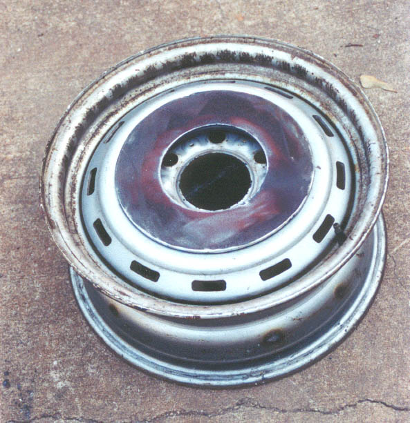 of the rim and pedestal will be filled with concrete so it is necessary
to cut a hole in the center of the reinforcing plate where the pipe column
will be installed to allow concrete into the pedestal. Set the reinforcing
plate as it will be assembled and measure the distance between the ground
and the top of the reinforcing plate. Deduct this dimension from the total
desired height to determine the length of the column. Cut the column to
this length.
of the rim and pedestal will be filled with concrete so it is necessary
to cut a hole in the center of the reinforcing plate where the pipe column
will be installed to allow concrete into the pedestal. Set the reinforcing
plate as it will be assembled and measure the distance between the ground
and the top of the reinforcing plate. Deduct this dimension from the total
desired height to determine the length of the column. Cut the column to
this length.
The size of the top is based on the size of the grinder and anything
else you may wish to allow for. This particular pedestal was sized to accommodate
a cup for cooling water. If you are using 1/2" plate no reinforcing will
be necessary. Lighter material (5/16" or less) for the top will require
that you weld reinforcements to the underside to achieve the required stiffness.
Flame cut the top to final size. Grind the cut to cleanup. To get a smooth
cut on the straight sides I clamp a straightedge offset from the cut by
1/2 the width of the torch tip. Then I drag the torch down the straightedge
to make the cut. This gives a much straighter cut, which requires little
grinding to cleanup. I then go back and radius the corners freehand.
The water cup holder is made from a 3" length of 3" schedule 40 pipe
(3-1/2" OD). It so happens that a discarded eight-ounce yogurt cup fits
the inside diameter of this pipe nicely. The yogurt cups work well since
they don't rust and can be easily replaced when damaged. Cut the pipe to
length and dress the ends. Using the 3" pipe as a template layout a hole
at the desired location in the top. Flame cut the hole. The hole needs
to be large enough to clear the 3" pipe. Check the hole with the pipe.
If the hole is near the edge it will probably cause some distortion in
the top plate. Hammer the distortion back into shape. Grind any slag at
the cut. Insert the pipe into the hole with about 1/2" extending above
the top. Tack weld in three places at 120(. Make sure the pipe in square
and positioned correctly. Run a continuos bead between the pipe and top
plate. This weld will be visible in the final product so take the time
to make it look good.
Place the top upside down at a comfortable height to weld the column
to the top. Place the column in position. I try to center the column under
the grinder motor since that is the bulk of the weight. Tack weld the column
to the top in three places at 120(. Check for square and weld continuos
between the column and the top.
Place the bottom reinforcing ring at a comfortable height. Center the
column on the ring. Tack weld in three places at 120(. Check for square
and adjust as required. Place the bottom reinforcing ring on the rim in
position. Check the top for level and adjust. Tack weld the bottom reinforcing
ring to the rim in three places. Recheck level of the top. Weld out the
column to the reinforcing ring. I skip weld the reinforcing ring to the
rim. Usually six evenly spaced welds about 3" long are sufficient. Clean
any slag from the welds with a wire brush.
Turn the whole assembly upside down. Cut four 3/8 or 1/2" round bars
to make a grid across the inside of the rim. Rebar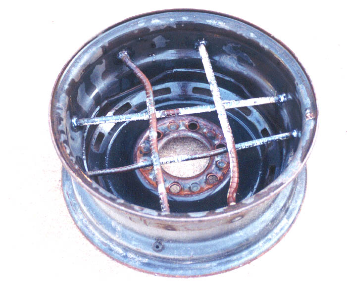 works best but smooth bar is OK also. Weld the four bars into the inside
of the rim. These bars will help to hold the concrete in place.
works best but smooth bar is OK also. Weld the four bars into the inside
of the rim. These bars will help to hold the concrete in place.
Now is the time to clean up the outside for painting. I usually wire
brush any loose rust or paint and then apply a metal prep solution.
Turn the entire assembly upside down and support well. I use a pipe
stand to keep it from tipping over. Mix one 60# bag of Sakrete. Shovel
into the base. Use a stick or rod to work concrete into the column. Let
the concrete set overnight.
The wheel assembly consists of two brackets, an axle sleeve, an axle
and two wheels. Make the axle assembly first. The sleeve is 1/2" pipe or
3/4" pipe 12" long. If 3/4" pipe is used weld two 1/2" washers on each
end to reduce the diameter to about 1/2". The wheels are 6" lawnmower wheels
with a 1/2" bore. Use 1/2" cold rolled steel for the axle. Determine the
length by inserting the 1/2" rod through the wheels and axle. Leave enough
on each end for cross drilling for cotter pins. Mark and cutoff the axle.
Cross drill for cotter pins on each end. Make the brackets from 3/16" X
1-1/2" flat bar. Bend to approximately 90(. Adjust position of bracket
against rim so axle sleeve is located about at the bend in bracket. It
may be necessary to trim brackets. Tack both brackets to rim. Weld out
brackets to rim.
Clean entire assembly and paint. Since this is to be used indoors,
the paint is more for appearance than for weather protection. One can of
spray paint is usually sufficient. The cheap stuff works fine. Bolt the
grinder to the top and you are ready for a test drive.
