Volume 8, No 8 - August, 2003
|
|
Volume 8, No 8 - August, 2003 |
|
|
|
|
|
| President - |
Vice President - |
||
| Treasurer - |
Secretary - |
||
| Webmaster - |
Editors - |
||
| Founder - |
SIG Coordinator - |
Statement of Purpose
Membership is open to all those interested in machining metal and tinkering with machines. The club provides a forum for the exchanging of ideas and information. This includes, to a large degree, education in the art of machine tools and practices. Our web site endeavors to bring into the public domain written information that the hobbyist can understand and use. This makes an organization such as this even more important.Regular Meeting
 At
the Collier Library, 6200 Pinemont, Houston, Texas, July
12, 2003, 1:00 pm. Tom Moore, President, presiding. There were 30 persons present
including one visitors, Todd Garver.
At
the Collier Library, 6200 Pinemont, Houston, Texas, July
12, 2003, 1:00 pm. Tom Moore, President, presiding. There were 30 persons present
including one visitors, Todd Garver.
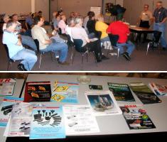
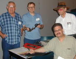
Shown at the left, members bring literature and catalogues that are duplicates or that they're finished with for others to take. Please bring back checked out library books so the next person can get a chance at them. We have about 25 books in the library of which only 3 - 4 make it back each meeting. If you are unable to make a meeting, please mail them to me, Dennis Cranston, 9134 Wilcrest Dr. Houston, TX 77099
Election of club officers was held. The results
are shown below.
Election Results - Club Officers for 2003-4
|
|
|
|
|
|
|
|
|
Members News
|
HMSC member John Robb died July 2, 2003. |
|
Long time HMSC member David Whittaker has temporarily (maybe permanent) moved to Chicago, Ill. |
Business Meeting
Minutes are sent via email or regular mail to club members.
Presentation
 The
program was a video on making guns in Afghanistan. It showed how an entire
city was involved in making weapons using basic hand operated machinery
plus a motorized vertical mill operated by a youngster. Starting with
steel salvaged from old ships, they hand scribed the layout, torch cut the pieces, followed
a lot of filing. Heat treatment consisted of packing parts in a clay pot
filled with leather charcoal, sealing and firing it in a pit. This
gave the gun parts a surface or case hardening. Gun metal coloring was obtained by
dipping parts in boiling paint. Upon assembly, they walked outside and test
fired into the air. Everyone was armed and revenge was a tradition. They
also recycled old US and Soviet munitions and vehicles. This city was a
source for weapons for the Taliban. Looks like you don't need a 5-axis
CNC machine to make serviceable weapons.
The
program was a video on making guns in Afghanistan. It showed how an entire
city was involved in making weapons using basic hand operated machinery
plus a motorized vertical mill operated by a youngster. Starting with
steel salvaged from old ships, they hand scribed the layout, torch cut the pieces, followed
a lot of filing. Heat treatment consisted of packing parts in a clay pot
filled with leather charcoal, sealing and firing it in a pit. This
gave the gun parts a surface or case hardening. Gun metal coloring was obtained by
dipping parts in boiling paint. Upon assembly, they walked outside and test
fired into the air. Everyone was armed and revenge was a tradition. They
also recycled old US and Soviet munitions and vehicles. This city was a
source for weapons for the Taliban. Looks like you don't need a 5-axis
CNC machine to make serviceable weapons.
Show and Tell
|
|
|
|
|
|
|
No activity reported this month.
Computer Numerical Control SIG

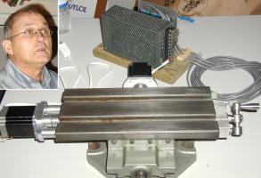 Charlie Mynheim showed
his CNC milling table he build that can fit on a drill
press or mill table. It costs under $500. He
replaced the original lead screws with ball screws and the end bearings with thrust
bearings. The table is intended to mount on a Bridgeport using the Bridgeport's
z-axis manually. Along with his table, he brought his stepper motor driver
(Xylotex) and power supply module Charlie was asked
to put plans for it the web projects page. reported
by Dennis
Cranston
Charlie Mynheim showed
his CNC milling table he build that can fit on a drill
press or mill table. It costs under $500. He
replaced the original lead screws with ball screws and the end bearings with thrust
bearings. The table is intended to mount on a Bridgeport using the Bridgeport's
z-axis manually. Along with his table, he brought his stepper motor driver
(Xylotex) and power supply module Charlie was asked
to put plans for it the web projects page. reported
by Dennis
Cranston
 The novice group met, and fortunately, the "experts" outnumbered the "novices". Advice flowed freely. Several sources for literature and
web sites were discussed. A machining textbook
was donated to the library. Rich Pichler brought his toolbox. and the
tools that he has were discussed. Almost all of Rich's tools were obtained at garage sales over
several years
The novice group met, and fortunately, the "experts" outnumbered the "novices". Advice flowed freely. Several sources for literature and
web sites were discussed. A machining textbook
was donated to the library. Rich Pichler brought his toolbox. and the
tools that he has were discussed. Almost all of Rich's tools were obtained at garage sales over
several years
Rich's Tool Box Contents
Chip brush;
Steel
rules, 6 & 12-in..; Dividers; Hermaphrodite caliper; Outside calipers, 4-in.& 8-in.;
Inside calipers, 4-in. & 8-in.; Outside Micrometer 1 & 2 in.; Inside micrometer, Dial
caliper , 6-in.; Telescope gauge
set; 12-in. Square w/protractor & center head; Feeler gauge; Protractor, Dial indicator w/stand;
Files, assorted w/handles + card; V-block
set; Hacksaws w/12, 18, 24, & 32-tpi blades; Number drill set, 1-60; Pliers, slip,
needle nosed; Side cutter; Drill press w/clamps and vise; Vise grip pliers;
Bench grinder; Micrometer standards; Chisels; Wire
gauge; Center & prick punch; Optivisor & magnifying glass; Fractional
drill se, 1/16 - 1/2-in; Small hole gauge set;, Tap and Die set w/thread gauge; Layout fluid w/scriber;
Tapping fluid w/eye
dropper; Drill motor portable; Countersinks; C-clamps, assorted; Hammers,
ball pein 8-oz & brass; Bench vise 3-4-in; Reference Books, Tweezers: reported
by Rich Pichler
Featured Articles
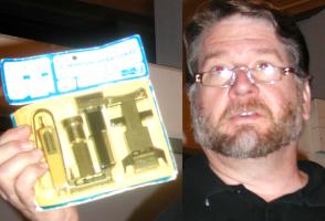
Quick-Connect Pneumatic Couplers
by
Dick Kostelnicek - HMSC Member
In ignorance, I often purchased the wrong air hose coupler socket or plug. Often, they just didn't interchange with the ones already in service in my shop. To me, all coupler styles looked alike! Varying quality often gave poor fit-up, and some just leaked right out of the box, especially when stressed at the connection. These are some of the problems I've encountered. So, I decided to learn about quick-connect couplers.
 The
three kinds of quick-connects are: 1. Straight-through
or valve-less: They provide the least resistance to fluid flow.
An example is those you attached to the threaded connections already on
garden hose. They don't hold pressure on either end when decoupled. 2. Double
shut-off or two-way: These have a valve in both the mating socket
and plug. The valves automatically close upon decoupling, thereby preventing fluid loss and pressure
drop in both ends. They are mostly used on hydraulic hoses. 3. Single shut-off or one-way:
This is the coupling covered here. It is widely used to connect pneumatic
hoses and tools. When uncoupled, a valve in the socket closes to prevent pressure
loss on the supply end of the hose, while on the plug end, the air tool is depressurized.
The
three kinds of quick-connects are: 1. Straight-through
or valve-less: They provide the least resistance to fluid flow.
An example is those you attached to the threaded connections already on
garden hose. They don't hold pressure on either end when decoupled. 2. Double
shut-off or two-way: These have a valve in both the mating socket
and plug. The valves automatically close upon decoupling, thereby preventing fluid loss and pressure
drop in both ends. They are mostly used on hydraulic hoses. 3. Single shut-off or one-way:
This is the coupling covered here. It is widely used to connect pneumatic
hoses and tools. When uncoupled, a valve in the socket closes to prevent pressure
loss on the supply end of the hose, while on the plug end, the air tool is depressurized.
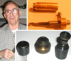
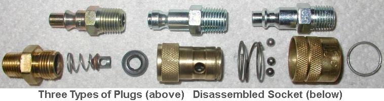
Quick-connect pneumatic couplers are composed of two parts; socket and plug. The socket attaches to the air supply hose and should mate with any plug attached to an air tool. The above photo shows three plug styles. In order of increasing frequency of use (as pictured left-to-right) they are: ARO Interchange (Ingersoll Rand), True-Flate (Automotive) Interchange, and Industrial Interchange. I'll drop the word Interchange from the coupler designations, since it means only that plugs and sockets of the same designation or style must mate regardless of who manufactured them. In my experience, however, this is not strictly true. Cheap couplers often yield poor fit-up.
Each coupler style comes in three sizes or capacities. 1/4, 3/8, and 1/2-in. The
size refers to the air flow capacity. Coincidentally, it also refers to
the approximate plug tip diameter but not the pipe thread
on the coupler's end. A 1/4-in. coupler will drop the pressure by 1-psi at a
flow of 10-cfm and 5-psi at 20-cfm. They are all pressure rated
well above 90 psi, and therefore, are suitable for most individual hand
operated air
tools. A 1/4-in. coupler usually has 1/4-in. NPT threaded connection. Male
or female threads are available on both sockets and plugs. I buy only female
threaded sockets and keep a few close nipples on hand for the rare case
when I need a male threaded socket. Also, I use more
male than female threaded plugs. The plugs are made of plated hardened
steel. Sockets come in both brass and plated hardened steel. I prefer brass
sockets outdoors, where rusting is a problem, and steel
sockets in my shop, since they are less prone to impact damaged when a hose is dropped on
the floor after disconnecting.
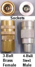
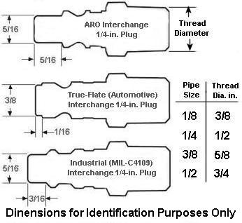 The
ARO style connector is found in industrial maintenance facilities.
True-Flate is used in most automotive
shops. The Industrial style is ubiquitous, especially in
the home workshop. It is even stocked at my local home improvement center. The approximate
tip dimensions for 1/4-in. plugs are shown in the diagram at the left. I keep
one of each of the three plug styles in my car for identification purposed and
so that I can test mate them with the couplers that I purchase. Recently, the
Universal socket has become widely available (also at my local home improvement
center). It accepts all three plug styles and cost just a fraction more
than a single acceptance style socket. The coupler is made up by pulling back a spring
loaded sleeve on the socket with the fingers of one hand, inserting the
plug to full engagement with the other hand, and finally, releasing the
sleeve. This procedure allows a ring of latch balls to expand radially into a
recess in the sleeve, the balls then slip over a boss on the plug, and finally drop-in
and secure the balls into the plug groove as the sleeve is released. Couplers come
with 3, 4, and 6 balls. I try to buy 4-ball sockets, as they are in my price
range and give adequate performance. The sockets that accept only
a single style plug usually have
a spring-loaded tubular valve that is opened when the tip of the
plug is inserted. Referring to the cut-away view of the quick-connect shown above, the plug
tip seals on its end as it comes in contact with a rubber seal washer. The other
side of this washer is the seat for a tubeular valve that has been pushed back
off of the washer seat.
If the plug is poorly manufactured or its tip is damaged, the seal will leak.
When the coupler is stressed by bending, often due to the weight of the
hose, the washer-to-plug tip seal can leak. I prefer the Universal couplers, that mate with all
three plug styles. They use "O" rings as radial seals
rather than relying on a rubber washer as an end seal. As an added
advantage, Universal couplers can be made up with one hand. The sleeve
is automatically pushed back as the plug is inserted. Of course, you must pull
back on the sleeve to disconnect.
The
ARO style connector is found in industrial maintenance facilities.
True-Flate is used in most automotive
shops. The Industrial style is ubiquitous, especially in
the home workshop. It is even stocked at my local home improvement center. The approximate
tip dimensions for 1/4-in. plugs are shown in the diagram at the left. I keep
one of each of the three plug styles in my car for identification purposed and
so that I can test mate them with the couplers that I purchase. Recently, the
Universal socket has become widely available (also at my local home improvement
center). It accepts all three plug styles and cost just a fraction more
than a single acceptance style socket. The coupler is made up by pulling back a spring
loaded sleeve on the socket with the fingers of one hand, inserting the
plug to full engagement with the other hand, and finally, releasing the
sleeve. This procedure allows a ring of latch balls to expand radially into a
recess in the sleeve, the balls then slip over a boss on the plug, and finally drop-in
and secure the balls into the plug groove as the sleeve is released. Couplers come
with 3, 4, and 6 balls. I try to buy 4-ball sockets, as they are in my price
range and give adequate performance. The sockets that accept only
a single style plug usually have
a spring-loaded tubular valve that is opened when the tip of the
plug is inserted. Referring to the cut-away view of the quick-connect shown above, the plug
tip seals on its end as it comes in contact with a rubber seal washer. The other
side of this washer is the seat for a tubeular valve that has been pushed back
off of the washer seat.
If the plug is poorly manufactured or its tip is damaged, the seal will leak.
When the coupler is stressed by bending, often due to the weight of the
hose, the washer-to-plug tip seal can leak. I prefer the Universal couplers, that mate with all
three plug styles. They use "O" rings as radial seals
rather than relying on a rubber washer as an end seal. As an added
advantage, Universal couplers can be made up with one hand. The sleeve
is automatically pushed back as the plug is inserted. Of course, you must pull
back on the sleeve to disconnect.
 Sockets
are attached to the pipes and hoses that supply pressurized air, and never
to the tool itself. Plugs can be directly screwed into the tool
or attached to the opposite
end of an extension hose. Because a large amount of compressed air is stored
in an extension hose, take care when a plug is removed from the supply
connected socket. The charge of air, stored in the hose, will violently
jet it away from the socket. This is called hose whip, and can
cause bodily injury and property damage. Use two hands, stand aside of
the connection, and where eye protection when disconnecting a pressurized connector. You
can obtain special plugs that have an internal ball check valve that eliminates
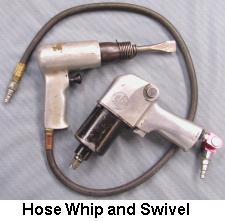
hose whip, but also restricts air flow. Hose whip also has another
meaning. On tools such as an air chisel or impact wrench, the plug should
not be directly attached to the tool, but rather via a short length of flexible
hose
called a whip. This arrangement prevents the impulsive shock from the tool
from damaging or shaking loose
the coupler as might happen if it were directly connected to the
tool. Hose whips are standard on air chisels. I recommend their
use on all air tools. They are usually 2-ft in length, inexpensive, and readily
available at supply houses. Hose whips also prevent the quick-connector from being stressed as the air tool is maneuvered into
various positions. They can also reduce the tool's carrying weight; the result
of a heavy extension supply hose. Additionally, a 2-axis swivel can allow
the tool to rotate and move about without twisting the supply hose. Hose whips and
swivels provide an added margin of safety in potentially dangerous
situations.
Sockets
are attached to the pipes and hoses that supply pressurized air, and never
to the tool itself. Plugs can be directly screwed into the tool
or attached to the opposite
end of an extension hose. Because a large amount of compressed air is stored
in an extension hose, take care when a plug is removed from the supply
connected socket. The charge of air, stored in the hose, will violently
jet it away from the socket. This is called hose whip, and can
cause bodily injury and property damage. Use two hands, stand aside of
the connection, and where eye protection when disconnecting a pressurized connector. You
can obtain special plugs that have an internal ball check valve that eliminates
hose whip, but also restricts air flow. Hose whip also has another
meaning. On tools such as an air chisel or impact wrench, the plug should
not be directly attached to the tool, but rather via a short length of flexible
hose
called a whip. This arrangement prevents the impulsive shock from the tool
from damaging or shaking loose
the coupler as might happen if it were directly connected to the
tool. Hose whips are standard on air chisels. I recommend their
use on all air tools. They are usually 2-ft in length, inexpensive, and readily
available at supply houses. Hose whips also prevent the quick-connector from being stressed as the air tool is maneuvered into
various positions. They can also reduce the tool's carrying weight; the result
of a heavy extension supply hose. Additionally, a 2-axis swivel can allow
the tool to rotate and move about without twisting the supply hose. Hose whips and
swivels provide an added margin of safety in potentially dangerous
situations.
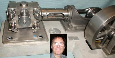
Eccentric Drilling / Turning
in a 3-Jaw Chuck
by J. R. Williams - HMSC Member
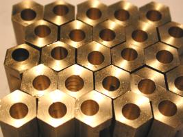
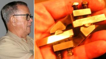
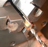 I
needed to drill an off-center hole in a number of brass clamp parts as shown in
the left hand photo. The material is 3/8-in. hex brass with a #10 drilled
hole. This can be done in a 4-jaw chuck, providing the part is not
too small for the jaws. However, my chuck's jaws were just too big.
I
needed to drill an off-center hole in a number of brass clamp parts as shown in
the left hand photo. The material is 3/8-in. hex brass with a #10 drilled
hole. This can be done in a 4-jaw chuck, providing the part is not
too small for the jaws. However, my chuck's jaws were just too big.
Using a 4-jaw requires careful layout of the work and jaw adjustment. The classic method of offsetting work requires the use of a dial indicator with a wiggler set in the depression of a pre-punched center hole. The chuck is rotated by hand and adjustment made to the jaws till the wiggler's point is stationary. The process is only as accurate as the original punched hole's location, and is time consuming, especially when repeated for many identical parts.
Alternatively, a flat shim, 0.050-in. thick in my case, can be placed between the work and one jaw of a 3-jaw chuck. The shim offset my work by nearly the desired amount. After adjusting its thickness with a few hammer blows, the desired offset was reached.
Several years ago I made an eccentric pin for a tail stock adjustment
on a metal spinning lathe using this same method.
 comment by Dick Kostelnicek- HMSC Member
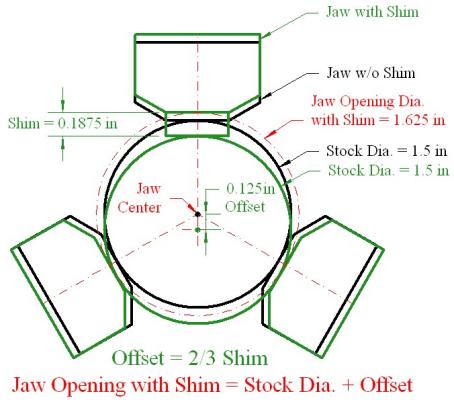
Upon reading about Joe Williams' offset turning technique, I wanted to know if I could determine the shim thickness directly from the desired offset. So, I did the math and came up with the formula: OFFSET = 2/3 SHIM THICKNESS. An example is shown in the diagram at the right. Incidentally, putting the same thickness shims on two of the jaws gives the same offset as a single shimmed jaw.
This formula is good for both hex and round stock as long as the round stock does not shift so far that it falls off the edge of a jaw's flat. Hex stock is more forgiving. Its flats, effectively, extend the contact with the flats on the jaws so it can take a larger offset than round stock of the same diameter. Although I haven't tried it, round stock less than 1-1/8-in. dia. could be held in a 5C hex collet block and offset with a shim against the block.
The new jaw opening for a given offset is given by the formula: JAW OPENING = STOCK DIAMETER + OFFSET. In the case of hex stock, use across-the-flats as the stock diameter.
Joe measured his shim thickness as 0.055 in., which calls for
an offset of 2/3 x 0.055 = 0.036. His measured offset was
0.033-in.
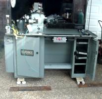
A Large Numerically Controlled Router Table
by Bill Swann - HMSC - Member
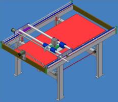
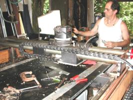 My router
table has a cutting area of 6-ft. x 3-ft. x 9-in vertical motion. The 3-D
design drawing is shown at the left and the actual machine on the right.
My router
table has a cutting area of 6-ft. x 3-ft. x 9-in vertical motion. The 3-D
design drawing is shown at the left and the actual machine on the right.
Computer control is used on all three axis. My software comes from www.abilitysystems.com. All axis are driven by stepmotors and drivers from Pacific Scientific. I micro-step each axis with 10000 steps per inch; a single step = 0.0001-in. However, since I built the table from components that I had on hand, I know that the lead accuracy in the long horizontal direction is only +/- .001-in. per ft. The lead screw accuracies on the remaining axis are unknown.
This router table is different than all those that I have seen, in that the vertical axis motion is affected by moving the work table up and down, while the router's vertical position remains stationary. Vertical motion is caused by a stepmotor belted to four Duff-Norton screw jacks. A disadvantage of this technique is the cost, and having to move a large amount of weight. This can be compensated for by adding four air cylinders to counterbalance the table and work's dead weight. A design advantage is that additional vertical stroke can be added to the overhead router when necessary. This method of construction makes for a structurally stiff cutter platform
I planned for two cutter heads: 1. A drop in Porter-Cable
router. 2. A lower RPM DC motor driving a spindle made from a
modified large disk drive. This spindle has a 1/2-in. bore and
set screw to hold the cutter.
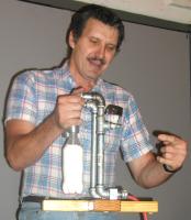
Moving a Lathe with Bed Rollers
by
Joseph Scott - HMSC Member
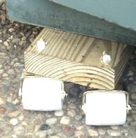
 I have a pea-gravel driveway making it difficult to move
my lathe outdoors in order to gain additional temporary shop
floor space. Most wheels that will carry a substantial
load are 6-8 in. diameter. But, that is too high
for jacking up and placing under my lathe. I found some
low profile bed rollers rated at 300-lb. each. The tangs of
four rollers were slipped into drilled holes
in a wood 2X6 that was placed under each end of the lathe,
for a total of eight rollers under the machine (total cost $20 at
my local home improvement store). The lathe moved easily
with a single driver (me). I plan to revise this setup to lower lathe closer to floor and leave it
under
machine
I have a pea-gravel driveway making it difficult to move
my lathe outdoors in order to gain additional temporary shop
floor space. Most wheels that will carry a substantial
load are 6-8 in. diameter. But, that is too high
for jacking up and placing under my lathe. I found some
low profile bed rollers rated at 300-lb. each. The tangs of
four rollers were slipped into drilled holes
in a wood 2X6 that was placed under each end of the lathe,
for a total of eight rollers under the machine (total cost $20 at
my local home improvement store). The lathe moved easily
with a single driver (me). I plan to revise this setup to lower lathe closer to floor and leave it
under
machine
|
Visit Our Web Site |
 |
Right click below then select [Save
Target As...]
From Netscape select [Save Link As..]
Microsoft
Word version of this newsletter 448 KB