Volume 9, No 12 - December 2004
|
|
Volume 9, No 12 - December 2004 |
|
|
|
|
|
| President - |
Vice President - |
||
| Treasurer - |
Secretary - |
||
| Webmaster |
Editors - |
||
| Founder - |
SIG Coordinators - |
Statement of Purpose
Membership is open to all those interested in machining metal and tinkering with machines. The club provides a forum for the exchanging of ideas and information. This includes, to a large degree, education in the art of machine tools and practices. Our web site endeavors to bring into the public domain written information that the hobbyist can understand and use. This makes an organization such as this even more important.Comming December Presentation
Joseph Scott will present a short color movie of rifle making, circa 1941.
Regular Meeting
 Collier Library, Houston Texas, November
13, 2004, 1:00 p.m., Doug Chartier - Vice President, presiding. There were 33 members
attending with 4 guests; Ross Cook, Dave Wintz, John Zackary, Preston
Engebretson.
Collier Library, Houston Texas, November
13, 2004, 1:00 p.m., Doug Chartier - Vice President, presiding. There were 33 members
attending with 4 guests; Ross Cook, Dave Wintz, John Zackary, Preston
Engebretson.
Doug Chartier mentioned that he is the new list owner of jobshophomeshop@yahoo.com discussion
group. Richard Pilcher was singled out for kudos for his efforts in the Novice
SIG. Anyone with something to share is encouraged to do so.
Business Meeting
Minutes are sent via email or regular mail to club members.
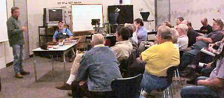
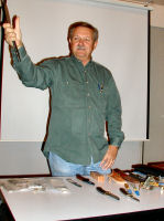
Presentation
|
|
|
The presentation this month was given by Jim Lemcke, owner of Texas Knifemakers supply. He discussed his available products and services. He went on to talk about different materials for blades, handles and the different types of knife kits. He also discussed the results of heat treating blades including cryogenic tempering in liquid nitrogen
Special Interest Groups Activity:
Novice Group
|
|
Casting SIG
The next casting session to be at Zube park in early December was discussed.
Show and Tell
|
|
|
Featured Articles
More on the Auto Parts Store
Demise
by Paul Munsel (N5XMV) - Franklin, Texas
I am fortunate that I live in a small town here in Texas. We have a local parts store that was one like you mentioned using for all those years ( see last months article by Dick Kostelnicek). I too have watched the changes though. It is Hearne Auto Supply. When I first started using them about 25 years ago, they had a small but very efficient machine shop. They could do the drums and rotors, but also do anything needed for an engine short of the boring, and that was farmed out to a full blown machine shop in Cameron. The machinist, Will Petty, decided he was old enough to retire, so a replacement for him was found. An older gray haired gentleman Fred did a good job, and the machine shop was expanded, and more equipment was purchased. I was allowed to do anything in the shop I needed to do, and was sometimes called upon to do things they had no idea how to do (sometimes I didn't either, but I did it anyway). Keith Jentsch, the owner, is a good friend for many years, and he had the older counter guys, and a couple of younger kids like you mentioned. I have watched the store grow, and change with the times. I was always able to get anything I needed there, from body shop supplies to machine work items (including tools etc), and all kinds of auto parts including for my '50 8N tractor, lawn mower, and chain saws.
Well, as with everything else, they have changed... All of the lumber yards closed. Then the Western Auto closed. There were no hardware stores closer than the Bryan/College Station area. Keith closed the machine shop, and started to remodel. We do have a lot of hardware now. He has just expanded again, and we have even more! He can still get me specialty items for my home machine shop. He even sends folks to me for small specialty work (it is a hobby, and I refuse to take money for my time, only materials.)
Did I tell you we have HARDWARE now? Well, I got the last roll of brass shim stock a couple of weeks ago. Keith's son-in-law gave it to me, and said that is the last of it. He said they were not going to re-order, as I was the only one any more who used it... I talked to Keith, and he said he would still order it for me, but it would have to be in whatever quantity it was sold to him. Well, better than nothing... I go in looking for items to use on bike maintenance, and most of the guys run when they see me. I am usually looking for something they have no idea about, and it would be too much trouble to learn about it. One of the senior guys really does try to help folks, but is limited to what he knows they have. Another fella my age is there for a check it seems. There is one young fella, about 20, who is really interested in helping folks, and wants to learn. Unfortunately, I am afraid he will lose interest do to some of the others. You know it is bad, when they tell the customers they don't have something, and never did and I walk over, and get it for the customer, or tell them where it is. If you don't want to help the public, get out of the way!!!!!
Anyway, I can still get the ignition wire for now like you wanted. If you
still need some, let me know what it is, send me a digital picture etc, and
I'll see what I can do. I appreciate what you guys have posted on your web site,
and I'll visit often.
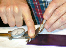
Determining the Bolt
Circle from a Chord
by Dick Kostelnicek - HMSC Member
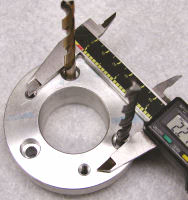
 While
installing a new table drive for my mill's crossfeed, I needed to make a special
mounting spacer. The supplied manufacture's spacer had three holes on a bolt
circle of unspecified diameter, as shown in the left photo. The problem was to
determine the diameter of the bolt circle from a measure of the distance between
two of the three holes, commonly called a chord distance.
While
installing a new table drive for my mill's crossfeed, I needed to make a special
mounting spacer. The supplied manufacture's spacer had three holes on a bolt
circle of unspecified diameter, as shown in the left photo. The problem was to
determine the diameter of the bolt circle from a measure of the distance between
two of the three holes, commonly called a chord distance.
I placed two snug fitting pins into two of the three holes. For pins, I used the shanks of two drill bits. If the holes had been tapped, I could have screwed in two SHCS or socket head cap screws with Teflon taped threads to make a snug fit. Then, I measured the distance "X" spanned by the pins ( see photo at left ), and subtracted from it the pin diameter "S". Refer to the drawing at the right for the distance designations. The chord length "C" is given by C = X - S.
Now it is not necessary to measure the chord distance between two adjacent holes in order to find the bolt circle diameter "D". Any two holes will do. But, you will attain more accuracy by using the largest chord possible. In fact, when the number of holes is even, the chord can be determined directly using diametrically opposite holes. Let's call the number of evenly spaced bolt holes "N" and the number of spaces between the two inserted pins "M". In the drawing N = 5 and M = 2. The diameter of the bolt circle is then given by the following formula:
D = C / sin(180 M / N)
The angle for the trigonometric sine is given in degrees. There is more on the chord of a circle at http://mathworld.wolfram.com/CircularSegment.html. The following table gives a value to multiply C by for various M and N values in order to determine D.
| M = 1 | 2 | 3 | 4 | 5 | 6 | 7 | |
| N = 3 | 1.1547 | ||||||
| 4 | 1.4142 | 1.0000 | |||||
| 5 | 1.7013 | 1.0515 | |||||
| 6 | 2.0000 | 1.1547 | 1.0000 | ||||
| 7 | 2.3048 | 1.2790 | 1.0257 | ||||
| 8 | 2.6131 | 1.4142 | 1.0824 | 1.0000 | |||
| 9 | 2.9238 | 1.5557 | 1.1547 | 1.0154 | |||
| 10 | 3.2361 | 1.7013 | 1.2361 | 1.0515 | 1.0000 | ||
| 11 | 3.5495 | 1.8497 | 1.3232 | 1.0993 | 1.0103 | ||
| 12 | 3.8637 | 2.0000 | 1.4142 | 1.1547 | 1.0353 | 1.0000 | |
| 13 | 4.1786 | 2.1518 | 1.5080 | 1.2151 | 1.0695 | 1.0073 | |
| 14 | 4.4940 | 2.3048 | 1.6039 | 1.2790 | 1.1099 | 1.0257 | 1.0000 |
| 15 | 4.8097 | 2.4586 | 1.7013 | 1.3456 | 1.1547 | 1.0515 | 1.0055 |
| 16 | 5.1258 | 2.6131 | 1.8000 | 1.4142 | 1.2027 | 1.0824 | 1.0196 |
Spot Welder
Development
by J. R.Williams - HMSC Member
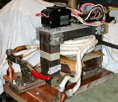
 A spot welder can be a handy item in a shop but one that
never seemed to be so important as to warrant laying down hard cash. After many my years of
collecting stuff, I decided a fair sized transformer that has
been moved around too may times might be a candidate for a spot welder. After a few power checks I decided on which
winding to retain and took the reciprocating saw to the other windings. After considerable time spent sawing and a
little hammer work, I had a large core with a primary winding. The dimensions of the core and a few quick
calculations indicated the project might work A secondary winding was wound in place using 2/O welding cable
and the length on hand filled the core space. With 120 volts on the primary, tests indicated the unit should be
reconnected to 240 volts. The primary
has about 190 turns of rectangular number 10 copper wire. Another length of cable was secured, but there was not enough open
core space to use the cable with the heavy rubber jacket. The jacket was stripped off and the wire
was wound with woven cotton tape without any adhesive. Not having any adhesive on the cable makes
it much more flexible and easier to handle. This gave me two windings for the secondary that are connected in
parallel. The open circuit voltage
with 240 volts on the primary is 6.25 volts. The next step was to fabricate a base using canvas filled phenolic
material with a slot cut to position a lower copper bus bar. The Destaco clamp was a natural for the
toggle mechanism. Things were now
taking shape but trial runs indicated the voltage and current was not
correct. Another inspection of the
transformer core showed two spacers that appeared to be coil spacers and
supports but were actually laminated steel material forming a magnetic shunt. Back to the hammer and punch and I
removed the
shunts. The unit was then rewired to
install a solid state relay with a push button and a short interval timer. Now I was at the limit of the capacity of
the solid state relay (25 amp on 120 volts) leaving the next step to obtain a
higher voltage rated relay. Reconnecting the supply side to 240 volts showed the new relay (25 amp
at 240 volts) was not sufficient in capacity as I was now drawing 35 amp at 240
volts. The solid state equipment was
removed and replaced with a mechanical circuit breaker. Now the unit works manually. Further modification to the system will be
to replace the cable solder lugs with larger ones, change the design of the electrodes
a little to make adjustment simpler, tie the secondary winding to stop movement
and go to solid state controls.
A spot welder can be a handy item in a shop but one that
never seemed to be so important as to warrant laying down hard cash. After many my years of
collecting stuff, I decided a fair sized transformer that has
been moved around too may times might be a candidate for a spot welder. After a few power checks I decided on which
winding to retain and took the reciprocating saw to the other windings. After considerable time spent sawing and a
little hammer work, I had a large core with a primary winding. The dimensions of the core and a few quick
calculations indicated the project might work A secondary winding was wound in place using 2/O welding cable
and the length on hand filled the core space. With 120 volts on the primary, tests indicated the unit should be
reconnected to 240 volts. The primary
has about 190 turns of rectangular number 10 copper wire. Another length of cable was secured, but there was not enough open
core space to use the cable with the heavy rubber jacket. The jacket was stripped off and the wire
was wound with woven cotton tape without any adhesive. Not having any adhesive on the cable makes
it much more flexible and easier to handle. This gave me two windings for the secondary that are connected in
parallel. The open circuit voltage
with 240 volts on the primary is 6.25 volts. The next step was to fabricate a base using canvas filled phenolic
material with a slot cut to position a lower copper bus bar. The Destaco clamp was a natural for the
toggle mechanism. Things were now
taking shape but trial runs indicated the voltage and current was not
correct. Another inspection of the
transformer core showed two spacers that appeared to be coil spacers and
supports but were actually laminated steel material forming a magnetic shunt. Back to the hammer and punch and I
removed the
shunts. The unit was then rewired to
install a solid state relay with a push button and a short interval timer. Now I was at the limit of the capacity of
the solid state relay (25 amp on 120 volts) leaving the next step to obtain a
higher voltage rated relay. Reconnecting the supply side to 240 volts showed the new relay (25 amp
at 240 volts) was not sufficient in capacity as I was now drawing 35 amp at 240
volts. The solid state equipment was
removed and replaced with a mechanical circuit breaker. Now the unit works manually. Further modification to the system will be
to replace the cable solder lugs with larger ones, change the design of the electrodes
a little to make adjustment simpler, tie the secondary winding to stop movement
and go to solid state controls.
Mental-urgy (Part - 2) Practical Metallurgy for the Home Machinist
By Vance Burns - HMSC Member
 A2
is an air-hardening steel providing justifiable cost benefits - nominal sizes
require no quenching, thus avoiding thermal shock, and low quenching/hardening
demands deliver superior results for beginners. In reality, the quenching process
is still present, and the quenchant is ambient air. Within industry, liquid
submersion of A2 is practiced; quenching requirements are influenced by mass
- you will not quench your A2 bowling ball in still air. Your metals manufacturer
will always shave the exact procedure available for a given material, contact
them by phone or on the web. On average, we will heat a piece of A2 round, 2
x.75 in. to about 1400/1450F, the ramp up taking about 30 minutes. Then
pour on the coal and bring it up to 1750F, soak for 20 minutes, then set it
aside in still air to cool. Leave the piece alone and temper the operator with
an adult beverage. You will see a hardness which will skate a file, about 64
Rockwell. Of course there is under and over heating questions, and while not
impossible to ruin a piece, most air hardening steels are tolerant, but be safe,
and be careful. An ounce of prevention will always be cheaper than tool steel.
Look at the graphic at the left. optimally the sample must be below 1350F
in under 6.5 minutes - depending on your mass, this will probably happen without
intervention. During this time you can tweak the dimensions for up to
15 minutes, and then cool it off under an hour. This piece will be incredibly
hard, yet very brittle. If your application justifies, and the cross sections
permit, you might not temper your piece, or you might rethink and go with shock
resistant steel, the air hard S series. Most samples will need to be softened
(tempered) slightly. Tempering to 59 Rockwell requires about two hours at 600
degrees. Let it cool, then re-temper. Setting overnight in the deep-freeze,
between temperings, does have some benefits. Some experimentation has shown
the home deep-freeze can add demonstrable toughness at higher Rockwell. This
is most evident in very thin cross sections, i.e. blades and cutters. A liquid
nitrogen soak will provide measurable results, but until they start refilling
liquid nitrogen dewars at Kroger, I’ll settle for the fridge. One item to note is machining
hardenable steels; any of them will heat to hardenable temperatures under an
aggressive cut. With even low mass, they will self quench, forming nuisance
hard spots. Air hardening steels have greater potential, and require complete
concentration.
A2
is an air-hardening steel providing justifiable cost benefits - nominal sizes
require no quenching, thus avoiding thermal shock, and low quenching/hardening
demands deliver superior results for beginners. In reality, the quenching process
is still present, and the quenchant is ambient air. Within industry, liquid
submersion of A2 is practiced; quenching requirements are influenced by mass
- you will not quench your A2 bowling ball in still air. Your metals manufacturer
will always shave the exact procedure available for a given material, contact
them by phone or on the web. On average, we will heat a piece of A2 round, 2
x.75 in. to about 1400/1450F, the ramp up taking about 30 minutes. Then
pour on the coal and bring it up to 1750F, soak for 20 minutes, then set it
aside in still air to cool. Leave the piece alone and temper the operator with
an adult beverage. You will see a hardness which will skate a file, about 64
Rockwell. Of course there is under and over heating questions, and while not
impossible to ruin a piece, most air hardening steels are tolerant, but be safe,
and be careful. An ounce of prevention will always be cheaper than tool steel.
Look at the graphic at the left. optimally the sample must be below 1350F
in under 6.5 minutes - depending on your mass, this will probably happen without
intervention. During this time you can tweak the dimensions for up to
15 minutes, and then cool it off under an hour. This piece will be incredibly
hard, yet very brittle. If your application justifies, and the cross sections
permit, you might not temper your piece, or you might rethink and go with shock
resistant steel, the air hard S series. Most samples will need to be softened
(tempered) slightly. Tempering to 59 Rockwell requires about two hours at 600
degrees. Let it cool, then re-temper. Setting overnight in the deep-freeze,
between temperings, does have some benefits. Some experimentation has shown
the home deep-freeze can add demonstrable toughness at higher Rockwell. This
is most evident in very thin cross sections, i.e. blades and cutters. A liquid
nitrogen soak will provide measurable results, but until they start refilling
liquid nitrogen dewars at Kroger, I’ll settle for the fridge. One item to note is machining
hardenable steels; any of them will heat to hardenable temperatures under an
aggressive cut. With even low mass, they will self quench, forming nuisance
hard spots. Air hardening steels have greater potential, and require complete
concentration.
Next month – Heat’er up on a budget.
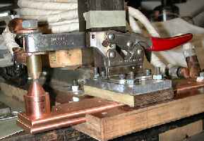
C-Clamp Pad
Replacement
by J. R.
Williams - HMSC Member
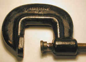
 I finally took
the time
to make a replacement pad and screw for a heavy duty C-clamp. The screw was made from a standard 3-1/2-in.
long, 3/8-in. socket head cap screw, and required the threads to be extended. The pressure pad was made from a section of
B7 stud stock and has a ľ-in. diameter face. A groove was cut in the end of the screw with a matching groove in the
inside of the pad. A retaining wire
ring was shaped from a ring from a spring to fit in the groove and when the
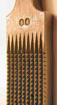
unit was finally assembled, the pad was firmly secured to the screw. The face of the Pad was checkered with a
pattern at 90 deg by use of a hand file and flame hardened before
assembly. The upper left photo shows the C-
Clamp assembly, below it is a close up of the Pad Face with the checkered
face. The right hand photo is a close up of the checkering file used on the
pad. The file is an old one I have
had for many years. These files are a
standard item in the Gun Smith Trade and are expensive.
I finally took
the time
to make a replacement pad and screw for a heavy duty C-clamp. The screw was made from a standard 3-1/2-in.
long, 3/8-in. socket head cap screw, and required the threads to be extended. The pressure pad was made from a section of
B7 stud stock and has a ľ-in. diameter face. A groove was cut in the end of the screw with a matching groove in the
inside of the pad. A retaining wire
ring was shaped from a ring from a spring to fit in the groove and when the
unit was finally assembled, the pad was firmly secured to the screw. The face of the Pad was checkered with a
pattern at 90 deg by use of a hand file and flame hardened before
assembly. The upper left photo shows the C-
Clamp assembly, below it is a close up of the Pad Face with the checkered
face. The right hand photo is a close up of the checkering file used on the
pad. The file is an old one I have
had for many years. These files are a
standard item in the Gun Smith Trade and are expensive.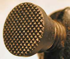
Ed Note: The use
of a checkering file in gun smithing can be found at http://www.brownells.com/aspx/NS/General/DisplayPDF.aspx?f=Inst-277.pdf.
You may have to save this pdf file to your disk before viewing it in Acrobat
Reader.
|
Visit Our Home Page at |
 |
Right click below then select [Save
Target As...]
From Netscape select [Save Link As..]
Microsoft
Word version of this newsletter 265 KB