Volume 7, No 2 - February, 2002
|
|
Volume 7, No 2 - February, 2002 |
|
|
|
|
|
|
President - |
Vice President - |
||
|
Treasurer - |
Secretary - |
Ed Gladkowski |
|
|
Web Master - |
Editors - |
Membership Information
Membership is open to all those interested in machining metal and tinkering
with machines. The purpose of the club is to provide a forum for the exchanging
of ideas and information. This includes, to a large degree, education in
the art of machine tools and practices. There is a severe shortage of written
information that a beginning hobbyist can use. This makes an organization
such as this even more important.
Business Meeting
Minutes are sent via email or regular mail to members.
Regular Meeting
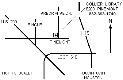
1:00 p.m., January 12, 2002 at Collier
Library, 6200 Pinemont, Houston, Texas, President Dennis Cranston
presiding. There were 30 + attendees,
including visitors Brian Alley, Ed Katz, Mark Smiley and Chuck West.
It was announced that the proposed swap meet be held the same day as the regular meeting in March, with the swap meet in the morning followed by the regular meeting at its normal time in the afternoon. Full details will be promulgated at the February meeting.
Presentation
|
|
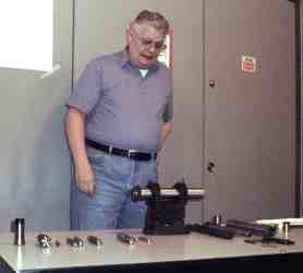
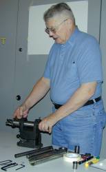
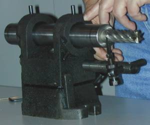
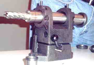
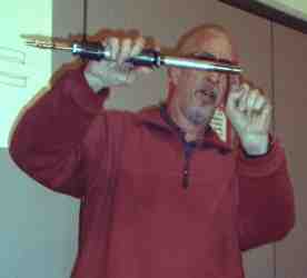
Tom Moore - HMSC member, demonstrated equipment, ways and means, for sharpening end mills. |
|
|
|
|
Show and Tell
|
Joe Scott explained how he resolved the collet problems he spoke about last Month, by heat treating and �springing� a cheap collet. |
Larry Hill showed an experimental propane burner for this freon tank foundry furnace.The burner is partly based on one Art Volz showed last month, to which Larry added his own modifications. |
Ray Ethridge showed his first very worthy attempt at metal casting: a model engine flywheel. |
|
|
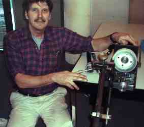
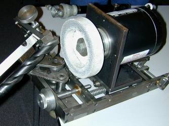
John Hoff demonstrated his drill sharpner, a "Work in Progress" . He retipped a 1" dia drill to perfection. |
|
|
|
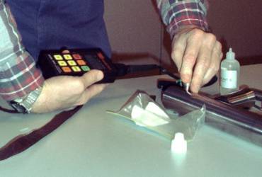
Richard Pilcher demonstrated ultra sonic thickness testing. |
|
Bill Swann - HMSC member - and his large wood lathe/router operation. He has a ten foot long octagonal wood "Glue-lam" beam that started as 12 inches across going for 10 inches on one end and tapering to eight on the other. All under computer control. What you do not see is that Bill's left hand is on a E-Stop button. Also the RPM was only about 15 (4 sec. per rev.). Of course he would put on his safety glasses if it were turning faster. |
photo credit: J.R.Williams |
|
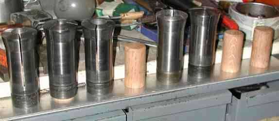
Collet Rack |
I frequently use the 5C collets in my lathe and may have several out of the storage drawer at one time. The temporary parking place has been to stand them up on the top of a drawer case. Then the fun would begin as I have knocked several over and even down to the floor. I do have a rubber mat on the floor to prevent damage to dropped items and help the old man's feet and legs. I solved the problem by fabricating a working storage rack using sections of hardwood dowels and screwing them to a section of 1/4 inch thick aluminum plate. The plate fits between the drawer case and a wall mounted shelf. The dowels were lathe turned to clear the base of the collet and a heavy coat of paste wax was applied before final assembly.
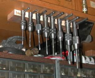
| Tap
Wrench Holder |
|
|
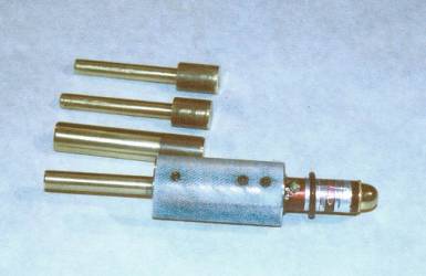
Laser Bore Sight
by Keith Mitchell
- HMSC member
 Sighting in guns can be
a time consuming process. Frequently, if starting from scratch, it can be a
challenge to get a gun shooting on the paper so the final sight adjustments can
be made. You sometimes need an observer just to tell you where the last shot
hit. Also when sighting in you would like to use the minimum number of rounds
to avoid heating the barrel. Bore sights are a rough alignment tool to get you
on target the first shot. This tool can
also be used in the field to verify your sights have not been jarred off during
travel or handling.
Sighting in guns can be
a time consuming process. Frequently, if starting from scratch, it can be a
challenge to get a gun shooting on the paper so the final sight adjustments can
be made. You sometimes need an observer just to tell you where the last shot
hit. Also when sighting in you would like to use the minimum number of rounds
to avoid heating the barrel. Bore sights are a rough alignment tool to get you
on target the first shot. This tool can
also be used in the field to verify your sights have not been jarred off during
travel or handling.
 I had always thought a bore sight would be nice to have.
After punishing my shoulder with 15 rounds through a muzzleloader to get it on
target I was convinced it was time to get serious. Bore sights are available
commercially. They run in the $50 to $100 range. I had felt for some time they
could be made from a laser pointer.
I had always thought a bore sight would be nice to have.
After punishing my shoulder with 15 rounds through a muzzleloader to get it on
target I was convinced it was time to get serious. Bore sights are available
commercially. They run in the $50 to $100 range. I had felt for some time they
could be made from a laser pointer.
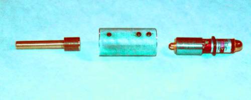
The Laser Bore Sight consists of four primary parts; the laser pointer, a laser pointer sleeve, the body and the insert. I have not given detailed drawings because none of the dimensions are critical.
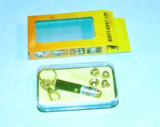
I bought the laser pointer from a local shop for $2.00. I've seen the same style other places also. It's probably best to buy several. I bought three and ended up with two that work. If the batteries are included frequently they are old and corroded. Make sure they work and the batteries are good before you pay for them.
 The body is made from 1in. dia. aluminum round bar. The
body has 1/2 in. bore in one end and a bore to match the laser pointer sleeve
on the other. Both of these bore diameters need to provide a close fit with the
mating part. If you feel the need to be
super accurate, both of the bores should be done on the same setup. The insert
end is drilled and tapped for one 8-32 X1/4 in. set screw. The laser pointer
end is drilled and tapped for two 8-32 X 1/4 in. set screws. I knurled the
body primarily to improve the appearance.
The body is made from 1in. dia. aluminum round bar. The
body has 1/2 in. bore in one end and a bore to match the laser pointer sleeve
on the other. Both of these bore diameters need to provide a close fit with the
mating part. If you feel the need to be
super accurate, both of the bores should be done on the same setup. The insert
end is drilled and tapped for one 8-32 X1/4 in. set screw. The laser pointer
end is drilled and tapped for two 8-32 X 1/4 in. set screws. I knurled the
body primarily to improve the appearance.
The laser pointer I bought was set up as a key chain. I removed all of the key chain parts. The back of the laser pointer screws off to replace the batteries. The laser pointer body is thin aluminum tubing, so I turned a sleeve from 3/4 in. CRS so the set screws that secure the laser pointer to the body would have something solid to bear on. The laser pointer is 0.525 in. O.D. I turned the sleeve OD to 0.650 in. The ID is bored for a sloppy fit on the OD of the laser pointer body. The sleeve is epoxied to the laser pointer at assembly. The slop in the sleeve I.D. is allowed to allow alignment at assembly.
The insert is turned from 1/2 in. dia. brass round bar. I used brass to make sure I don't damage the barrel crown or rifling. I gage the bore diameter of the rifle with a pin gage. If you don't have pin gages you might try turning a small taper near the required diameter to use as a gage. The insert should be a good sliding fit with as little clearance as possible. The better the insert fits the bore the more accurate the bore sight. I try to make the shoulder as square as possible so the radius doesn't catch the inside of the barrel bore. With most factory barrel crowns this is not a problem. The insert is held in the body with an 8-32 X 1/4 in. set screw. An insert is required for each different caliber. I identify my inserts by writing the caliber on the backside with a vibrating pen.
It probably took longer to figure how to calibrate this device than to build it. My initial thought was to use a gun that was already sighted in. Apply glue to the laser pointer and insert it into the sleeve. Then move the laser dot to the scope crosshairs and hold it there until the glue sets. This will work but there are some drawbacks. Keep in mind that bullets travel in a parabolic trajectory while light travels in straight lines. With a rifle sighted to shoot in at 200 yds. the bullet starts out below the line of sight, rises above the line of sight at about 50 yds. Is about 2 in. high at 100 yds. and drops back down to the line of sight at 200 yds. If you use the bore sight at 35 ft. chances are the laser dot will be below the line of sight. If you use it at 35 to 50 yds. it's probably close to the line of sight. So using this method will work but the calibration is good at only one distance.
 After trying my initial plan, I realized that an easier
way is to assemble everything and glue up the laser pointer. Insert the
assembly in the gun barrel as it would be in use and turn the whole assembly
while the gun barrel remains stationary. If the laser dot is stationary, it's
aligned with the barrel. If the laser dot moves in a circle, it is at an angle.
After trying my initial plan, I realized that an easier
way is to assemble everything and glue up the laser pointer. Insert the
assembly in the gun barrel as it would be in use and turn the whole assembly
while the gun barrel remains stationary. If the laser dot is stationary, it's
aligned with the barrel. If the laser dot moves in a circle, it is at an angle.
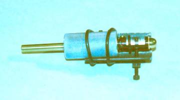
I used a short piece of 1 in. angle to make an alignment tool. It is drilled and tapped for two 8-32 screws. The angle is clamped to the body with two "O" rings. The bore sight assembly is inserted into a gun barrel. I like to glue in the laser pointer with the gun barrel vertical so the excess glue doesn't drip. I apply heavy grease to the insert and the body bore for the insert. If glue gets to the wrong place it's easy to remove. Glue is also applied to the O.D. of the laser pointer. The laser pointer is set in the body contacting the set screws. I use an "O" ring to hold the laser pointer against the alignment set screws. Rubber bands would also work. Initially the laser dot will make a circle. The laser pointer is operated by a miniature pushbutton on the side. I'm sure there are more elegant solutions but I use an "O" ring to clamp the switch in the ON position. The set screws are adjusted while the bore sight is turned in the gun barrel until the laser dot remains a dot as the bore sight is turned. My experience has been that the laser pointers are not very well aligned. The laser pointer will actually appear to be pointed at a noticeable angle. Thus the need for a sloppy fit between the sleeve and laser pointer body. Allow the glue to set and it's ready to use.
 To use the bore sight you simply insert the correct diameter
brass insert into the barrel and turn on the laser pointer. Look through the
sights to see where the sights are with respect to the laser dot. Then align
the sights to a point at the right relation to the dot based on the ballistics
of the cartridge and the distance being used. This works best in a low light
environment. I've used this bore sight at dusk over a distance of 100 ft. In full
sunlight that's not possible. I've also used it indoors at distances of 35 ft. I
always turn the bore sight in the barrel as was done in the initial alignment.
If the laser dot makes a circle because something is a little bit off, align
for the center of the circle.
To use the bore sight you simply insert the correct diameter
brass insert into the barrel and turn on the laser pointer. Look through the
sights to see where the sights are with respect to the laser dot. Then align
the sights to a point at the right relation to the dot based on the ballistics
of the cartridge and the distance being used. This works best in a low light
environment. I've used this bore sight at dusk over a distance of 100 ft. In full
sunlight that's not possible. I've also used it indoors at distances of 35 ft. I
always turn the bore sight in the barrel as was done in the initial alignment.
If the laser dot makes a circle because something is a little bit off, align
for the center of the circle.
|
The next meeting will be held on Saturday February, 9 2002 at the Collier Library 6200 Pinemont, Houston, TX at 1:00 pm. Bring along a work in progress. Visit Our Web Site |
 |