Volume 8, No 2 - February, 2003
|
|
Volume 8, No 2 - February, 2003 |
|
|
|
|
|
| President - |
Vice President - |
||
| Treasurer - |
Secretary - |
||
| Webmaster - |
Editors - |
||
| Founder - |
SIG Coordinator - |
Statement of Purpose
Membership is open to all those interested in machining metal and tinkering with machines. The club provides a forum for the exchanging of ideas and information. This includes, to a large degree, education in the art of machine tools and practices. Our web site endeavors to bring into the public domain written information that the hobbyist can understand and use. This makes an organization such as this even more important.
Business Meeting
Minutes are sent via email or regular mail to club members only.
Regular Meeting
 Collier Library, 6200 Pinemont, Houston, Texas. January
11, 2003. 1:00 pm. There were 40 attendees, 5 were guests; Joe Pappas, Todd
White, John Liestman, Bill Morgan, and Ray Stimac. They were welcomed and
invited to join as members.
Collier Library, 6200 Pinemont, Houston, Texas. January
11, 2003. 1:00 pm. There were 40 attendees, 5 were guests; Joe Pappas, Todd
White, John Liestman, Bill Morgan, and Ray Stimac. They were welcomed and
invited to join as members.
A list of non-renewing members was circulated to remind everyone that DUES ARE NOW DUE! Three new books for the circulating library were presented. Library books were on the table for members checkout. A different box of books will be brought each meeting. If you have a loan outstanding, please return it.
Next meeting program will cover designing and
torqueing fasteners for proper service.
Presentation

 Tom
Moore presented a program on threaded fasteners followed by Joe Scott's comments
on screws used in gunsmithing: The difference between a screw and a bolt
is that a bolt has a nut on it and a screw does not. They can be identical except
for this feature. Threads fall into three categories- assembly, fasteners
and transitional. Assembly threads are what are in cameras, for instance.
Fasteners are usually a standard thread and can fit many locations. Transitional
have some of both features. Threads were first standardized in Europe by the
English engineer Whitworth by averaging all the different threads used by English
manufacturers. They have a 55 deg. angle thread. The French, not wanting to use
English threads, devised the metric system. In America, Mr. Sellers set up the
first standards with 60 deg angle threads. Some of his numbered threads were
the same as used by American clockmakers. A fine thread was used for thin
materials. These threads became the American National Std. In
1920s the Society of Automotive Engineers set standards for class of fit and
dropped some of the in-between numbered threads. This enhanced mass production
of automobiles. They also set up an extra fine pitch, so that there were three
pitches; fine(SAE), US Standard(coarse) and EF(extrafine). There was also
a standardization effort by the US military to make threads common to their
needs. Sometimes you see reference to AN threads, they are Army-Navy Standards
and are no longer used. The 1903 Springfield rifle was based on the German Mauser
patent and its threads are the nearest inch conversion from metric, such as
1/4-25. In WWll, the odd threads were completely dropped and Unified threads
were established, such as UNC, UNF, UNEF with class of fit specified. Metric
threads have been standardized also. We now use ISO threads for many uses. A
general note: English threads use round roots and crests and are different
than ours. The English and Japanese still use 55 deg. angles for their
pipe threads. It is extremely hard to get our 60 deg. pipe thread to seal against
55 deg. Many of the cheap die sets have pipe dies and taps with 55 deg.
Check to see if it says NPT (60deg) before using. If it doesn't say anything, it is probably
55 deg.
Tom
Moore presented a program on threaded fasteners followed by Joe Scott's comments
on screws used in gunsmithing: The difference between a screw and a bolt
is that a bolt has a nut on it and a screw does not. They can be identical except
for this feature. Threads fall into three categories- assembly, fasteners
and transitional. Assembly threads are what are in cameras, for instance.
Fasteners are usually a standard thread and can fit many locations. Transitional
have some of both features. Threads were first standardized in Europe by the
English engineer Whitworth by averaging all the different threads used by English
manufacturers. They have a 55 deg. angle thread. The French, not wanting to use
English threads, devised the metric system. In America, Mr. Sellers set up the
first standards with 60 deg angle threads. Some of his numbered threads were
the same as used by American clockmakers. A fine thread was used for thin
materials. These threads became the American National Std. In
1920s the Society of Automotive Engineers set standards for class of fit and
dropped some of the in-between numbered threads. This enhanced mass production
of automobiles. They also set up an extra fine pitch, so that there were three
pitches; fine(SAE), US Standard(coarse) and EF(extrafine). There was also
a standardization effort by the US military to make threads common to their
needs. Sometimes you see reference to AN threads, they are Army-Navy Standards
and are no longer used. The 1903 Springfield rifle was based on the German Mauser
patent and its threads are the nearest inch conversion from metric, such as
1/4-25. In WWll, the odd threads were completely dropped and Unified threads
were established, such as UNC, UNF, UNEF with class of fit specified. Metric
threads have been standardized also. We now use ISO threads for many uses. A
general note: English threads use round roots and crests and are different
than ours. The English and Japanese still use 55 deg. angles for their
pipe threads. It is extremely hard to get our 60 deg. pipe thread to seal against
55 deg. Many of the cheap die sets have pipe dies and taps with 55 deg.
Check to see if it says NPT (60deg) before using. If it doesn't say anything, it is probably
55 deg.
Show and Tell
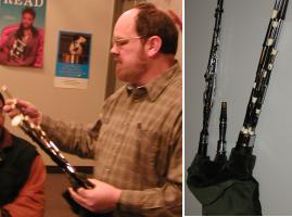
John Liestman displayed his Irish style bagpipe which he makes and played it for us. It is not played with the mouth but with the fingers. Air is supplied with a bellows under your arm. A really neat item. See more of his stuff at http://web.wt.net/~liestman. |
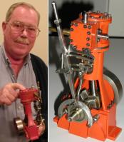
Bill Morgan displayed a small steam engine which he built. |
Ed Katz displayed a single large grown quartz crystal used to make electronic parts. |
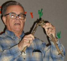
Joe Scott showed some old gun parts including a tripod for an old military gun. |
Don Rutledge displayed an electronic welding hood which he bought from Harbor
Freight. It was the $99 version and he likes it very well. |
Joe Williams displayed a book about screwdrivers. They are so old that the author could not document the origin of such a common tool. |
Jan Rowland, who doesn't like to show his mug in the newsletter, brought the mini toolpost air grinder that is featured in this months newsletter |
No activity this Month.
Computer Numerical Control SIG
 At CNC
Special Interest Group meeting, what the members were doing with CNC was
discussed. The question was posed about turning a servo system using Gecko's
without having a scope. No conclusions were reached.
At CNC
Special Interest Group meeting, what the members were doing with CNC was
discussed. The question was posed about turning a servo system using Gecko's
without having a scope. No conclusions were reached.
Update on Joe Williams' Shop Fire
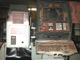
 Joe
Williams' shop suffered a disastrous file last November. Here is his progress
report. - editor.
Joe
Williams' shop suffered a disastrous file last November. Here is his progress
report. - editor.
The shop rebuild process is moving - very slow. The interior is finished and ready to get the power restored. I am in the process of installing new service to the house and that has to be finished before the power is connected to the shop. I have the new control (VFD) installed on the lathe and the tech from the mill supplier was out a couple days ago to firm up the parts required. I am going to dig a little deeper into my pocket and install a LCD monitor. 60 years of collecting 'stuff' makes for a lot of decisions when moving back into the shop. - Joe Williams - HMSC Member
Featured Articles
by Jan Rowland - HMSC Member
 The
availability of small pneumatic “die-grinders” from Harbor Freight (et al) for
less than $20 a copy inspires uses for those clearly not considered by their
manufacturers. One of those held in the proper position in the tool-post
of a lathe makes a useful small “tool-post grinder”, particular for I.D.-grinding
of short hollow parts, which might require an I.D.-finish not attainable with
the usual boring-bar operations.
The
availability of small pneumatic “die-grinders” from Harbor Freight (et al) for
less than $20 a copy inspires uses for those clearly not considered by their
manufacturers. One of those held in the proper position in the tool-post
of a lathe makes a useful small “tool-post grinder”, particular for I.D.-grinding
of short hollow parts, which might require an I.D.-finish not attainable with
the usual boring-bar operations.
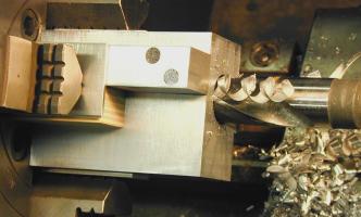
I find myself often conjuring chunks of material, which would probably be cast, if made in quantity, or by one of our Casting SIG. It is easier for this non-caster to bolt together a couple of pieces of stock, and then do a relatively small amount of machining on the result. In the left photo, we see such a piece held in a 4-jaw lathe-chuck for pre-drilling with a 1” diameter bit, in preparation for boring to final I.D.with one of the home-made boring-bars, photos of which were shown at the last meeting.
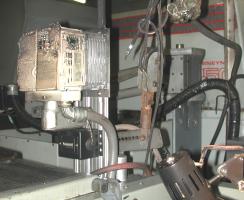
 The
right photo shows the completed holder with the die-grinder installed in
it, and a mounted point posed in the collet-chuck for show. What is not
visible is the O.D. of the die-grinder, which was very irregular as-purchased.
I turned the O.D. down to 1.275”, the largest I could keep it, still turning
all of its O.D. That cylinder is then held fast by two cap-screws installed
into the side not visible in the photos, which squeeze the holder tight on the
tool’s body. Note the valve-actuator on the right: The die-grinder
came with a “squeeze-lever” affixed with a roll-pin, this then pressing down
a plunger-valve-stem to admit shop-air.
The
right photo shows the completed holder with the die-grinder installed in
it, and a mounted point posed in the collet-chuck for show. What is not
visible is the O.D. of the die-grinder, which was very irregular as-purchased.
I turned the O.D. down to 1.275”, the largest I could keep it, still turning
all of its O.D. That cylinder is then held fast by two cap-screws installed
into the side not visible in the photos, which squeeze the holder tight on the
tool’s body. Note the valve-actuator on the right: The die-grinder
came with a “squeeze-lever” affixed with a roll-pin, this then pressing down
a plunger-valve-stem to admit shop-air. 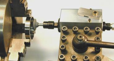 Removing
that roll-pin and lever reveals that stem, which protrudes only about an eighth
inch. Here I turned a 7/8” long extension, installed inside the aluminum
beneath that visible swinging actuator. Then, that actuator has an inclined
groove about an eighth inch deep at one edge, lessening to nothing on the other
side, so that the extension pushes on the stem as the actuator you see is rotated
CCW in this view. The aluminum protrusion near the bottom of the photo,
just above the 6” ruler, fits into the lathe’s tool-post as would any lathe-tool.
The axis-center of the grinder is at the same level as the top of the
lathe-tool would be.
Removing
that roll-pin and lever reveals that stem, which protrudes only about an eighth
inch. Here I turned a 7/8” long extension, installed inside the aluminum
beneath that visible swinging actuator. Then, that actuator has an inclined
groove about an eighth inch deep at one edge, lessening to nothing on the other
side, so that the extension pushes on the stem as the actuator you see is rotated
CCW in this view. The aluminum protrusion near the bottom of the photo,
just above the 6” ruler, fits into the lathe’s tool-post as would any lathe-tool.
The axis-center of the grinder is at the same level as the top of the
lathe-tool would be.
The final photo shows the rig posed in the lathe’s tool-post at work.
Cross Slide Holder for Vertical Bandsaw
by Dick Kostelnicek - HMSC Member
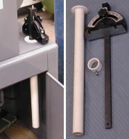 Here's
my solution for storing the cross slide used on a vertical bandsaw.
A 1-in. PVC (Poly Vinyl Chloride) pipe was cemented to a 2 in. diameter 1/4 in. thick PVC flange.
The flange was made from a 2-in. male to 1-in. female bushing that had enough "meat on it"
after turning. Plastic PVC machines
well with normal cutting tools on a lathe. A hole, slightly larger than
the pipe's OD, was cut through the top of the handsaw's pedestal base.
The PVC tube was dropped through the hole and secured from underneath by a slip-over PVC collar.
The collar was
made from a PVC pipe coupling,
with a set screw. The entry into the holder tube is well chamfered.
Here's
my solution for storing the cross slide used on a vertical bandsaw.
A 1-in. PVC (Poly Vinyl Chloride) pipe was cemented to a 2 in. diameter 1/4 in. thick PVC flange.
The flange was made from a 2-in. male to 1-in. female bushing that had enough "meat on it"
after turning. Plastic PVC machines
well with normal cutting tools on a lathe. A hole, slightly larger than
the pipe's OD, was cut through the top of the handsaw's pedestal base.
The PVC tube was dropped through the hole and secured from underneath by a slip-over PVC collar.
The collar was
made from a PVC pipe coupling,
with a set screw. The entry into the holder tube is well chamfered.
This plastic holder is soft enough so that it will not scratch
nor dent the cross slide. Also, the top of the PVC flange is a 1/4 in.
above the pedestal so that the cross slide's face never contacts
the metal top of the saw's base. Rather than make your own flange, as I did,
you can purchase a PVC tail piece for a sink drain which already has
a flange on it.
|
The next meeting will be held on Saturday February 8, 2003 at the Collier Library 6200 Pinemont, Houston, TX at 1:00 p.m. Bring along a work in progress to show. Visit Our Web Site |
 |
Right click below then select [Save
Target As...]
From Netscape select [Save Link As..]
Microsoft
Word version of this newsletter 229 KB