Mounting the Y axes sensor
Journal of the Home Metal Shop Club of Houston,
President - Keith Mitchell, V. Pres.- John Lilly, Treasurer - Gordon
Lawson, Secretary - Dean Eicher
Editor - Keith Mitchell Hm (281) 391-2406 Wk (713) 215-8123 Email kmitchl@wt.net
Membership Information
Notes from the President
By: Keith Mitchell
Our club has come a long way since it was founded. We have about fifty members and usually about 25-30 at the monthly meetings. Discussions during meetings result in participation by a number of people. We have a web page, which gets considerable exposure. Our newsletter compares favorably with any I've seen. These are all things of which we can collectively take credit. However, there is always room for improvement.
The things I would like to concentrate on for the next twelve months are 1) attracting new members and retaining the existing members, 2) improve the database of information available through the club and 3) establish a network with other clubs of similar interest.
New members are vital to keep our perspective fresh. Currently we advertise our club through the website; we leave copies of the newsletter on several suppliers' counters. When someone visits a meeting we send a complimentary newsletter for a few months to give them an opportunity to see what we are about. In addition to this I would encourage everyone to make the effort to welcome guest at our meetings. It's important that they feel comfortable. The last meeting was a good example. I was not able to meet either one of the guests as they were surrounded by other members. That's the way we want to be. My question to you is "What we need to do to improve in this area?"
Keeping existing members requires that we offer what you need. Here again I need your feedback. What can we add or delete which will better meet your needs?
I don't think a meeting goes by that someone does not request help with a problem they are currently experiencing. As stated on the first page of this newsletter written information on our interest is not readily available. Our current database consists of the video tapes we have collected, books and magazines which have been donated, and back issues of the newsletter. Perhaps we could add to what we have by developing a list of websites containing good information. I frequently find new sites with good information. To get this started please bring in a list of your favorite websites to the next meeting. Those who are not on the net can participate by suggesting a book or magazine which contains pertinent information.
The other aspect of improving our database is to develop a list of suppliers
for various materials. I think we all struggle from time to time getting
materials suitable for our projects.
Networking with other clubs will allow us to see what they are doing to keep their club viable. It may be possible to bring in guest speakers from other clubs to help with programs and benefit from new ideas.
If this seems ambitious it may be. However, how many of the members at the first meeting saw the club as it is today?
June Meeting Minutes
Reported by: Keith Mitchell
Chips Meeting - 1:00 P.M. June 19, 1999, Oak Forrest Library
Attendance - 28, Two first time attendees
In the Chips Meeting the following activities took place.
1. Past Issues of HSM and PIM - David Whittaker has been cataloging
the back issues of HSM , PIM, etc. Once cataloged, these will be available
for loan from the club library like the tapes and other publications. David
brought in a printout of the work in progress. David has done an excellent
job of listing each issue we have and the articles it contains.
2. George Marsden - brought in the small motors some of the members
had ordered.
3. Blind Auction - George King brought in an item for a blind auction.
Bidding started at $.25 and was closed at $.74 by Roy Cook. Roy now has
a classic oil can.
4. Taig Lathe - Vance Burns brought in brochures for Taig lathes.
5. Appreciation Plaque- John Korman had prepared an appreciation plaque
for George Carlson in recognition of his many contributions to the club.
Since John was unable to attend the meeting, Dean Eicher presented the
plaque.
6. Newsletter - Looking for volunteers for newsletter articles. We
have depleted the current supply down to two articles. We have two volunteers
who have agreed to assist those who want to do a newsletter article. Dean
Eicher will do CAD drafting. Jan Rowland is one of those multi talented
persons. He can help in almost any area. If you don't have all the necessary
skills we'll find the talent to publish your idea.
7. Nominations - The following were candidates for the hotly contested
election. President Keith Mitchell and Vance Burns; Vice President - John
Lilly and George Marsden; Treasurer - Gordon Lawson and W.G. Robinson;
Secretary - Dean Eicher and Bill Sperry. See page 1 of the newsletter for
election results.
8. Chipper Repair - George Marsden asked for ideas on repairing blades
for a limb chipper. It was suggested that he use hard facing rods to build
up the worn surfaces.
9. Bandsaw Blade Guide - George Carlson brought in a replacement bandsaw
blade guide. he had made.
10. Shop Crane - George Carlson requested input on a shop crane system
to service his mill and lathe. A number of ideas were put forward.
I had one job which required slightly more accuracy than I could hold using the graduation on the saddle of my lathe. After pricing some of the optical DRO (digital read outs) I decided to use the Shooting Star mechanical DRO. I talked to the engineer at the plant that makes them about the device for about 3 minutes. Then I ordered one. The company gladly took my credit card information. They paid the shipping cost and adjusted the bill from Canadian dollars to the quoted price. A week later a long skinny box arrive. I unpacked the box and looked through the instruction book. The book was written in very plain English and even had a few sketches. None of the sketches were of any help in figuring out how to mount the thing to my lathe. There were some brackets and screws to mount to a Sherline lathe. After a little head scratching and a few sketches I finally had a plan.
I hooked the telephone type connectors from the sensors into the display unit and plugged in the power supply to make sure the unit was working properly. After a few seconds of flashing the display unit went to all zeros. I had to loosen the shipping straps to get the display to change. In comparing the indicated direction to my original sketches the direction was backward on the cross slide. The manual did have a procedure for changing the indicated direction from the keypad during startup. It was easier to change my sketches at this point and permanently fix the problem.
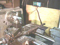
The following sketch and photo show how I attached the unit to a 13" Clausing Colchester lathe.
Mounting the Y axes sensor
On the cross slide of the Colchester lathe there is a V-grove with some
threaded holes this made a convenient place to mount a piece of 5/8" round
stock to get the spacing somewhat correct for the mounting of the sensor.
I cut a flat on one side and counterbored the mounting holes. I soon discovered
that the threaded holes in the cross slide were not centered or consistently
off center. Mounting the rod degenerated into a file to fit operation.
Next, I drilled several mounting holes in a piece of 1" X 1" angle iron
to be used as a chip guard. I positioned the angle iron and marked the
location on the flat of the rod. I removed the rod. Then I drilled and
taped the mounting holes for the angle iron. The saddle had mounting holes
intended for a taper attachment that made a convenient place to attach
the fixed portion of the DRO. I measured for, cut, and slotted a 4" X 4"
a piece of angle iron to mount and protect the electronic sensor. The total
time for this assembly was around 6 hours.
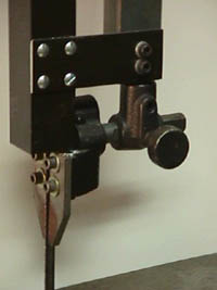
Mounting the X axes sensor
On the X-axis, the electronic sensor moves with the saddle and the rack is fixed. A two piece bracket attaches the sensor the saddle. The rack is protected by a 1" X 1" piece of angle iron. This was extremely simple compared to the Y-axes. The total time for this assembly was around 2 hours.
Setting the DRO is easy. Press the Y (X) axis key, enter the number, and press the Y (X) axis key again.
I protected the cabling using some plastic loom from the local auto parts store.
I discovered that on boring operations the lathe cross slide can move as much as .002" under load. This is because of a belleville washer compressing. This has changed the direction I use to do boring operations.
The DRO has been in service for over 6 months with no problems.
In conclusion the device has worked well, is easy to use and is cheaper
than a travel dial or an optical DRO for my machine.
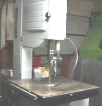
One of the most frequent tasks performed As Home shop machinists appears to be rebuilding machines. In the rush to get the machines into service, one is often tempted to install the personal protection guards latter. This is always a bad idea! Often the older equipment being rebuilt did not come with some of the modern safety features of the newer equipment. This was the case with my vertical band saw. I looked at the guards on the newer saws. I found two design problems with them. Fist, The guard had to be removed to change the blade. Second, The guards were supported on the bottom only and were too flimsy to provide a real sense of protection. I decided to build my own guard. Although I believe the guard shown in the following sketch is excellent for this machine, you must use your own common sense and good judgement when designing guards for your rebuilt machines
It is often desirable to have a fine adjustment on machines or tool grinders. Usually this means a fine thread. The most convenient way I have found is to adapt a cheap micrometer to your application. The thread pitch is almost always 40 TPI. Even in larger diameters fine threads are weak. Taps and dies are not readily available in fine or extra fine pitch in larger diameters. Fine threads are also notoriously bad for becoming clogged with all of the excellent contaminants found in the home machine shop.
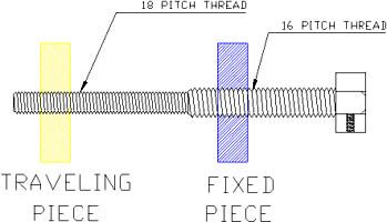 One possible solution
to this problem is to make a differential screw mechanism. Threading a
common shaft with two different thread pitches makes this screw mechanism.
As the shaft is turned the parts female parts move relative to each other
by the difference in the thread pitch.
One possible solution
to this problem is to make a differential screw mechanism. Threading a
common shaft with two different thread pitches makes this screw mechanism.
As the shaft is turned the parts female parts move relative to each other
by the difference in the thread pitch.
For example one screw has 16 TPI and the other screw has 18 TPI
P1 - P2 = 1/16 - 1/18 = .0069444 this is equivalent to having a screw
with 144 TPI.
Note that course threads are usually not cut accurately enough to yield
that kind of precision.
(See figure 1).
Possible design problems include:
Not being able to assemble the mechanism, this is not a problem if the
shaft size is stepped.
The mechanism goes the wrong direction when the shaft is turned.
Reference
Kinematic Analysis of Mechanisms 1959 McGraw-Hill Book Company, Inc
