Volume 8, No 3 - March, 2003
|
|
Volume 8, No 3 - March, 2003 |
|
|
|
|
|
| President - |
Vice President - |
||
| Treasurer - |
Secretary - |
||
| Webmaster - |
Editors - |
||
| Founder - |
SIG Coordinator - |
Statement of Purpose
Membership is open to all those interested in machining metal and tinkering with machines. The club provides a forum for the exchanging of ideas and information. This includes, to a large degree, education in the art of machine tools and practices. Our web site endeavors to bring into the public domain written information that the hobbyist can understand and use. This makes an organization such as this even more important.Business Meeting
Minutes are sent via email or regular mail to club members only.
Regular Meeting
 Collier Library, 6200 Pinemont, Houston, Texas, February
8, 2003, 1:00 pm. Tom Moore, President, presiding.
Collier Library, 6200 Pinemont, Houston, Texas, February
8, 2003, 1:00 pm. Tom Moore, President, presiding.
Thirty-nine persons were present, and several visitors, among
them were George Hawkins, Kelvin Marchant, and Tony Burnet. It was announced
that the molding bench at Zube Park is complete. President Tom Moore
stated that he has received inquiries from people wanting work done for
a fee. He asked if anyone was interested? Four people volunteered to accept
inquiries. The web master will post their contact information the HMSC web site.
Presentation
Joseph Scott on Torquing Fasteners
 Joseph
Scott covered torquing fasteners, continuing the nuts and bolts topic
started by Tom Moore last month. Fasteners work as solid springs holding something
together. Each size fastener and material has a different rating. Usually a
faster is stretched enough to hold the items together but not to yield or stretch
beyond its elastic limit. When a fastener yields, it is usually considered
to have failed. The amount of load in pounds divided by the effective cross
sectional area of the fastener gives the stress on the material. Usually, a
fastener is stressed right up to or near the yield point. As long as the yield
point is not reached, the fastener will return to original length. Different
materials or different grades of the same material have different design stress
levels. To get to the desired design stress level, fasteners are usually torqued
with a wrench. Hand wrenches are designed for the proper length to give adequate
torque with normal hand-arm pull. Most commercial fasteners are rated
to be torqued with an oil lubricant.
Joseph
Scott covered torquing fasteners, continuing the nuts and bolts topic
started by Tom Moore last month. Fasteners work as solid springs holding something
together. Each size fastener and material has a different rating. Usually a
faster is stretched enough to hold the items together but not to yield or stretch
beyond its elastic limit. When a fastener yields, it is usually considered
to have failed. The amount of load in pounds divided by the effective cross
sectional area of the fastener gives the stress on the material. Usually, a
fastener is stressed right up to or near the yield point. As long as the yield
point is not reached, the fastener will return to original length. Different
materials or different grades of the same material have different design stress
levels. To get to the desired design stress level, fasteners are usually torqued
with a wrench. Hand wrenches are designed for the proper length to give adequate
torque with normal hand-arm pull. Most commercial fasteners are rated
to be torqued with an oil lubricant.
Many applications require that a certain stress level of load be put on the fastener by either torquing or measuring the bolt stretch. Certain situations require that the bolt be stretched with a hydraulic puller, then the nut run down to seat before the pull is released. Torque is directly affected by lubrication, quality of threads, and surface finish of engaging faces. About 50% of the torque is used up by the flat surface of the nut. The balance is between friction of the threads and bolt stretch. On critical work, a hardened and ground washer is used under the nut.
Lubrication of threads is a study in its own right. Some very low friction lubes are not good for releasing after being in service. Solid based lubes; such as powdered metals, graphite, and Teflon; tend to release better than carbon based lubes, such as oil and grease. Powdered nickel or copper, with molybdenum added, are great for high temperature or all-around service.
Certain materials, such as stainless-steel, have a tendency to stick or gall together. These applications require a solid based lubricant that will not squeeze out. Most S-S fasteners are made of two different grades to reduce this tendency; e.g., 303SS bolt with a 305SS nut.
If you have an application with large heavy nuts that are hard to remove, you might consider cross-drilling the nuts on three sides through to the threads, installing zerk fittings to pump penetrating oil into the center of threaded area. It expands nuts and puts lube where it is needed.
Fasteners for airplanes are a different, as they are mostly designed to work in shear, rather than in tension, and are always used with some form of keeper or wire.
Many new applications, such as automotive use, overstress the fastener on purpose and they state that after removal, they not be replaced nor reused. Follow their advice! If you have to tighten a fastener excessively to make it hold, the design needs reviewing.
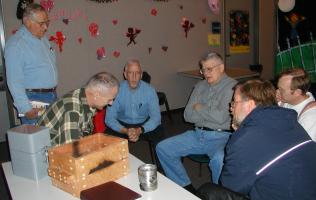
Show and Tell
|
John Lily showed an example of thread milling that both removed the bulk of the material and generated threads around the inner lip of an aluminum cover. |
Jan Rowland showed his tool post grinder made from a cheap Harbor Freight die grinder. "It takes more air than they claim for it." |
Ed Gladkowski showed his drill and tap jig for a 5/32-40 thread |
|
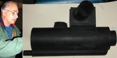
Visitor Tony Burnet displayed an air intake filter he is making for the WWII German Kubelwagon. He showed the forming dies and told how he heats the metal before forming it. It is an excellent reproduction. |
Joe Williams showed the melted CNC keyboard resulting from his shop fire. He also brought in and an electric motor driven die grinder used on his lathe. |
|
|
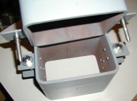
Ed Gladkowski showed his new and improved stackable flask
made from cut sections of rectangular tubing. Dick Kostelnicek brought
in a homemade maple wood flask that is held together with splines and 45-degree
corner bolts.
Computer Numerical Control SIG
No activity this Month.
Featured Articles
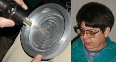
Live Center
for Centerless Shafts
John G. Korman - HMSC Member
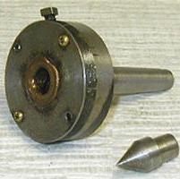
 At
the left is a picture of a live center made by my Dad over 50
years ago. He owned a machine shop and
garage and frequently overhauled auto generators and starters. One operation was to machine and true
the generator's
comuntator. In the 1930's, shafts for armatures
were centerless ground, and therefore, did not have a center hole for support
by a lathe's tailstock. To hold the shaft, he made
a live center
using a ball bearing with bushings for various size shafts. Remember, this was before live centers were
available commercially. I added the
shield, as chips often jammed the ball bearing.
I also made the 60-degree center plug adapter.
At
the left is a picture of a live center made by my Dad over 50
years ago. He owned a machine shop and
garage and frequently overhauled auto generators and starters. One operation was to machine and true
the generator's
comuntator. In the 1930's, shafts for armatures
were centerless ground, and therefore, did not have a center hole for support
by a lathe's tailstock. To hold the shaft, he made
a live center
using a ball bearing with bushings for various size shafts. Remember, this was before live centers were
available commercially. I added the
shield, as chips often jammed the ball bearing.
I also made the 60-degree center plug adapter.
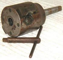
 I
also have a 2-jaw Skinner chuck. The jaws are V-shaped.
When meshed, they will accept both round and square stock. A web site
for this chuck is located at: http://www.lathechuckrepair.com.
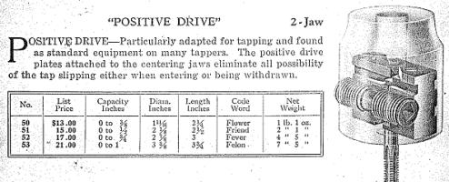
I've also included a photocopy from a Skinner catalog showing the inner
workings of the 2-jaw chuck.
I
also have a 2-jaw Skinner chuck. The jaws are V-shaped.
When meshed, they will accept both round and square stock. A web site
for this chuck is located at: http://www.lathechuckrepair.com.
I've also included a photocopy from a Skinner catalog showing the inner
workings of the 2-jaw chuck.
 Ed.
note: Joe Williams sent in the following:
Ed.
note: Joe Williams sent in the following:
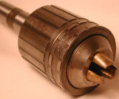
Here's a commercial version
of John's home built
armature chuck. The photo is of a "Jacobs Chuck No. 100, 1/4-3/4,
Center Rest" model. The jaws are bronze and set up for handling
round shafts. The chuck jaws are closed lightly on the work and then the front
ring is rotated to lock the jaws. Apply a little lube oil and get busy. I have an old Atlas Manual of Lathe Operation book that shows
the chuck in operation. The printing dates of the book are 1938 to 1954. -
Joe Williams - HMSC Member.
More Vertical
Band Saw Tips
by Dick Kostelnicek - HMSC Member
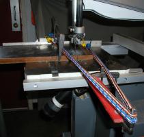
 Recently
I had to cut a 3/4 in. thick by 12 in. wide mild steel plate. The
work was too big to fit in my horizontal cut-off saw. So, I used the vertical
band saw. Pushing a 3/4 in. steel plate against the blade would have been a
trying and boring job. So I used some elastic cords to pull the work
through the saw unattended. The miter gauge and a bar clamp held and guided
the plate while the elastic cords applied the steady pressure against the
blade. I used my free time, while the machine did the cutting, to apply
wax lub to the blade and sweep up the shop floor.
Recently
I had to cut a 3/4 in. thick by 12 in. wide mild steel plate. The
work was too big to fit in my horizontal cut-off saw. So, I used the vertical
band saw. Pushing a 3/4 in. steel plate against the blade would have been a
trying and boring job. So I used some elastic cords to pull the work
through the saw unattended. The miter gauge and a bar clamp held and guided
the plate while the elastic cords applied the steady pressure against the
blade. I used my free time, while the machine did the cutting, to apply
wax lub to the blade and sweep up the shop floor.
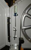
For easy access, and to ensure their safekeeping, I've put the hand-tools necessary for changing the band saw's blade inside the upper blade guard housing. The metric Allen key (it always got lost) is held in place with two small ceramic magnets. The Phillips screwdriver, used to remove the rear blade shield, is held in place with a snap-in broom handle clip.
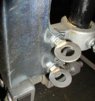 Being
metric, the two nuts that retain the front blade guard required my, often
misplaced, metric spin-tight nut driver. So, I silver soldered washers
into hacksawed slots in the guard's two hold down bolts. Now, I can remove
the blade guard with my fingers.
Being
metric, the two nuts that retain the front blade guard required my, often
misplaced, metric spin-tight nut driver. So, I silver soldered washers
into hacksawed slots in the guard's two hold down bolts. Now, I can remove
the blade guard with my fingers.
|
The next meeting will be held on Saturday March 8, 2003 at the Collier Library 6200 Pinemont, Houston, TX at 1:00 p.m. Bring along a work in progress to show. Visit Our Web Site |
 |
Right click below then select [Save
Target As...]
From Netscape select [Save Link As..]
Microsoft
Word version of this newsletter 219 KB