Volume 10, No 3 - March 2005
|
|
Volume 10, No 3 - March 2005 |
|
|
|
|
|
| President - |
Vice President - |
||
| Treasurer - |
Secretary - |
||
| Webmaster |
Editors - |
||
| Founder - |
SIG Coordinators - |
Statement of Purpose
Membership is open to all those interested in machining metal and tinkering with machines. The club provides a forum for the exchanging of ideas and information. This includes, to a large degree, education in the art of machine tools and practices. Our web site endeavors to bring into the public domain written information that the hobbyist can understand and use. This makes an organization such as this even more important.
March Program
Cloice Duncan from Houston Grinding and Manufacturing will
present a program on commercial thread forming using rollers instead of cutters.
The company rolls threads on compressor rods in excess of 15 feet in length
and 8 inches in diameter.
February Regular Meeting
 Collier
Library, Houston Texas, February 12, 2005, 1:00 p.m., Chuck West - President
presiding. There were 40 people attending, including 13 visitors: Richard Weeks,
Mike Gamberin, John Straniham, Louis Travino, Gary Cole, Mori Yubar, Bob and
Jenna Frenzel, Bill Peck, Mark Hunn, Richard Thomas, Douglas Baugher, and Maury
Vebelhor.
Collier
Library, Houston Texas, February 12, 2005, 1:00 p.m., Chuck West - President
presiding. There were 40 people attending, including 13 visitors: Richard Weeks,
Mike Gamberin, John Straniham, Louis Travino, Gary Cole, Mori Yubar, Bob and
Jenna Frenzel, Bill Peck, Mark Hunn, Richard Thomas, Douglas Baugher, and Maury
Vebelhor.
Doug Chartier, Vice President, discussed the format
of the day's show and tell - presentation and a possible cooperative
effort with the Collier library to show club member's projects in a few
months. He polled the membership concerning timing and participation.
Business Meeting
Minutes are sent via email or regular mail to club members.
Presentation - Show and Tell
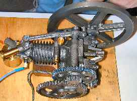
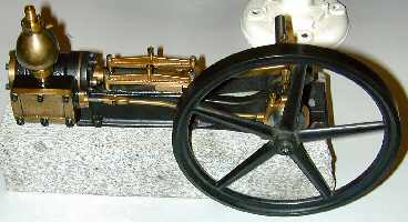
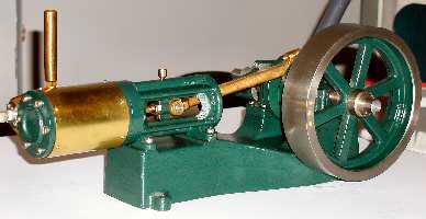
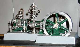
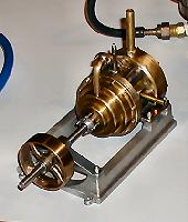
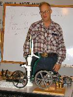
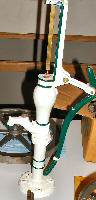
This month the presentation consisted of mostly steam engines built by members plus a few sundry other projects. Tables were set up around the room, and compressed air was provided. However, many presenters brought their own bottled air. The following pictures represent a collage of the presentations.
|
|
|
|
|
|
|
|
|
|
|
|
|
|
|
|
|
|
|
|
|
|
|
|
|
|
|
|
|
|
|
|
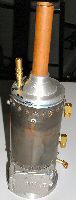
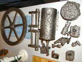
Dennis Cranston brought his model yard engine that is under construction and a model boiler.
Ray Ethridge showed and described the use of a bearing extractor.
Jan Rowland brought in and ran his small steam engine.
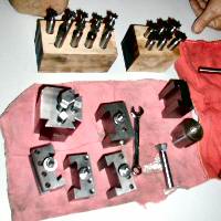
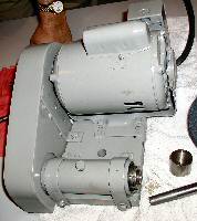
Joe Yeiser brought his home made toolpost grinder, a quick change tool post and some shop made dovetail cutters.
Dan Harper showed some hinges that he derusted by soaking them in tea.
Rob Lucas-Dean showed a split pattern for casting a blunderbuss barrel.
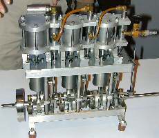
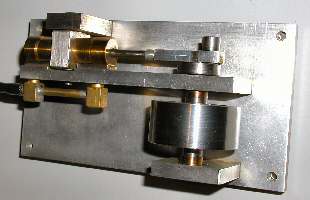
Dick Kostelnicek had a large display. A rather large double acting steam engine, He demonstrated it's operation in both directions with the same valve settings. A very nice triple expansion launch engine. A model Corliss stationary engine with discussion of the operation governor and valves that allow for "cut off" of the steam to make use of expansion. All of his models were under air power.
Joe Williams brought in a small Sterling engine and showed an elaborate valve seat cutter.
Leo Reed Showed and ran a small steam engine.
Maury Uberohl showed some of his steam engines, an air motor, a water pump and some castings he had done for him.
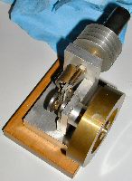
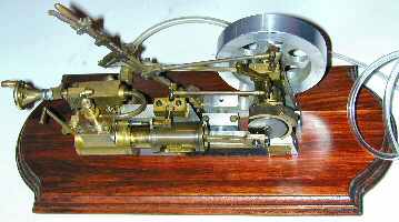
Ed Gladkowski brought and ran a model Colt steam engine, discussed it's rather peculiar mechanism, displayed the old pictures he made his plans from and some of the tools and patterns he used in it construction.
Steve Clay showed a Pot Broach used to cut grooves on the outside of some round parts.
Featured Articles
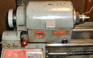
R8 Collet Adapter
for a 10-in. Rockwell Lathe
Bill Kleiman - Cedar Rapids Ia.
 |
 |
 |
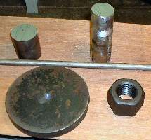
 After I read and looked at the pictures on the Home
Metal Shop Club web page about the use of R8 mill collets in lathes intended to
use 4C collets, I thought I would give it a try... especially when I've seen a set of
4C collets sell for $395 on E-Bay. I was a little concerned about cutting
internal threads on the nose closer, but I solved that problem by locating some 1-1/2 x
8 nuts at the Des Moines Nut and Bolt Co. in Des Moines, Ia. I faced off
both
surfaces of the nut while it was screwed on to the spindle so that they would be parallel to the
face of the spindle. Next, I undercut
the threads on one surface of the nut to a slip fit over the rear unthreaded
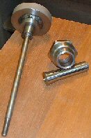
portion of the lathe's spindle. I then took a short 2-in. piece of stock and bored a
1/2-in. hole to accept
a short 1/2-in. round. This allowed me to support the 2-in round in the tail
stock's drill chuck and hold it tight against the outboard face of the
nut. I tack welded the two pieces together while held in the lathe. I then
removed the nut assembly from the spindle and finished welding the 2-in. stock to the nut. Then I
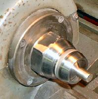
screwed the nut back onto the spindle and proceeded to turn it down to the
finished configuration with the exception of turning the internal nose closer taper. As the
compound on my lathe is not marked clearly in degrees, I inserted a collet
into the bare spindle and held it in place with the tailstock and used a dial
indicator against the collet's taper to set the compound angle. This gave me the exact angle
to cut the collet closer's nose taper.
After I read and looked at the pictures on the Home
Metal Shop Club web page about the use of R8 mill collets in lathes intended to
use 4C collets, I thought I would give it a try... especially when I've seen a set of
4C collets sell for $395 on E-Bay. I was a little concerned about cutting
internal threads on the nose closer, but I solved that problem by locating some 1-1/2 x
8 nuts at the Des Moines Nut and Bolt Co. in Des Moines, Ia. I faced off
both
surfaces of the nut while it was screwed on to the spindle so that they would be parallel to the
face of the spindle. Next, I undercut
the threads on one surface of the nut to a slip fit over the rear unthreaded
portion of the lathe's spindle. I then took a short 2-in. piece of stock and bored a
1/2-in. hole to accept
a short 1/2-in. round. This allowed me to support the 2-in round in the tail
stock's drill chuck and hold it tight against the outboard face of the
nut. I tack welded the two pieces together while held in the lathe. I then
removed the nut assembly from the spindle and finished welding the 2-in. stock to the nut. Then I
screwed the nut back onto the spindle and proceeded to turn it down to the
finished configuration with the exception of turning the internal nose closer taper. As the
compound on my lathe is not marked clearly in degrees, I inserted a collet
into the bare spindle and held it in place with the tailstock and used a dial
indicator against the collet's taper to set the compound angle. This gave me the exact angle
to cut the collet closer's nose taper.By first turning both surfaces of the nut and undercutting the threads to fit flush against the spindle collar, I was able to turn all remaining surfaces on the nose closer, including the taper for a zero indicator run out of the collet. The drawbar was easy to make. I welded it together. (see center photo above).
Editor's note of caution: Cover the lathe bed and other sensitive
lathe parts in order to prevent welding splatter from doing damage. Avoid
using the lathe bed as a welding ground, as the high currents flowing through
the headstock bearings may prove disastrous. Even with no direct welding
currents flowing through the lathe, induced (by transformer action) stray
currents might damage sensitive slides and bearings.
Mental-urgy (Part - 4) Practical Metallurgy for the Home Machinist
by Vance Burns - HMSC (Token Blacksmith) Member
Note: All the items mentioned in this atricle are inherently dangerous, and will exploit any opportunity to maim you. Metal working is dangerous, and can not be taken lightly. All gasses and chemicals called out in this essay typify stored energy, and potential bodily harm. Do not proceed without consulting professionals in your areas of interest.
How many times has this happened to you? You�ve spent hours making this or that, taken it to the furnace to heat treat, carefully calculate the time and energy required, executed your plan - only to come out with a train wreck!! You too? Well let�s spend some time together and explore solutions to one of heat treating�s most vexing problems.
With few exception, metals will corrode. Oxygen, both a bane and a benefit, will attack the materials we work with. By nature some are more susceptible � 01 steel rusts while you wait, while time will catch up with even the most exotic versions of stainless. Oxygen, ever vigilant, will take advantage of heat to accelerate this process, yet heat is our favorite tool for manipulating metal properties � what are we to do?
First, a little furnace science. Within the confines of an oxy/fuel furnace, metal should not corrode, for one would logically assume there is no free oxygen present to react with the metal surface. This is true if the gas is too rich, exactly at, or near the equilibrium of the fuel/oxygen balance. While this nexus varies from steel to steel, let�s assume we are within this zone, and all is proceeding. Typically, the steel will come up to temperature, and be withdrawn from the controlled atmosphere of the furnace/forge. As long as the steel (slight variations with type) is below 1000 degrees, oxygen will not bind with the steel significantly. If withdrawn above 1000 degrees, a thick oxide of iron will form, this is called scale. It is tenacious as anything you�ve yet encountered, will result in a measurable loss of desirable material, and visible dimensional change. Ick!
The only effective method for the the home shop machinist is to block oxygen�s access to the work piece. There are simple methods of dealing with this problem. Industry has some pretty slick solutions, but then Industry doesn�t operate within the limitations of your bank account. Common in heat treat shops is the stainless foil �wrap�. Priced at approximately $25 for a five foot roll, the .002 skin comes dear, and will cut you faster than a West Side Story switchblade. Anecdotal reports lead me to believe reuse of the foil is not recommended.
Industry makes great use of controlled atmosphere furnaces, and in his book Step By Step Knife Making David Boye outlines the concept of such a furnace. He simply introduces a low volume stream of inert gas into an electric furnace at high enough pressure to cause positive pressure, compensating for any leaks.
Very practical electric furnace designs exist, and a good example is Dave Gingery�s Lil Bertha; see http://www.lindsaybks.com/dgjp/djgbk/found.
Both salt and lead baths will answer in many cases, and certainly come in handy when tempering. Salt has many pluses; salt will be in intimate contact with all parts at the same time (even heating) and permits zero oxygen contact, even when the piece is withdrawn; parts are generously coated with a smooth salt skin. Common table salt operates at about 1470F and doesn�t get randy for another thou. SaltPeter is more operable, starting down in the 600�s. Lead melts in the low 600�s, and boils at +/- 3000F. The downside is - both can be toxic (lead assuredly) and if trapped moisture is present on your piece, they will give you a burn you will never forget.
The perceptive reader will recall - this is elemental physics; the ancients come to grips with these difficulties before industrial enlightenment. If one were to review my essay on Japanese swords, found on the club website (July 2000) you would learn about sophisticated atmospheric protection practiced long ago. Common backyard clays and soils served the pre-industrial metal smith. There is a bit of mystique about the properties of these clays, but the essential quality was to say where put � as long as it sticks, it blocks atmospheric access. A learned blacksmith, Don Fogg (dfoggknives.com) taught me that commercially available refractory compounds (e.g Satanite) used in furnace lining/repair could be employed. These powders are fine, and applied as a wetted slurry, adhere well, following minute surface irregularities. These properties allow regulation of thickness, and thus fine-tuning for insulative action in quenchants � a desirable control mechanism for spot hardening. Obviously, they also create an oxygen barrier.
Another method is akin to the antique carburizing technique; contain the part in an enclosure while within the furnace. You need not hermetically seal the enclosure; in fact one is cautioned to not do so as it is quite dangerous. All that is required is an envelope of some material which will hold up for the duration your work piece is in the furnace, and here is the trick, place a carbon/hydrocarbon within the chamber, in direct contact with the work piece. What will work? Several concoctions have been used, newspaper (pre carbon), coal, charcoal, WD40, and my favorite, horse manure. Lest you think I jest, remember that hooves and leather scraps were common in early steel making, and deemed essential to getting the color just right on Colt six shooter bluing. You goal is to consume all free oxygen while in the furnace and, since the container is not sealed, consume any free oxygen that might invade. In an oxy/fuel furnace, the carbon/hydrocarbon need not survive for the duration of the furnace time, so long as the furnace atmosphere is balanced, or slightly fuel rich. In a muffle furnace, or electric furnace, better results will follow if there is sufficient carbon material present, or you use the makeshift atmospheric furnace mentioned above.
Oil Can Base
by
J. R. Williams - HMSC Member
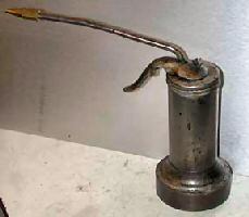 How many times have you found your oil can knocked over and
leaking oil all over the work bench? I
solved, or reduced, the problem by machining a heavy base and soldering it to
the base of the oil can. In this case,
it was a section of cast iron bar stock about an inch high. The top of the base was machined with a
reduced section for the rim of the oil can to fit into, thereby, centering the can. The oil can went through my shop fire only
loosing the nozzle.
How many times have you found your oil can knocked over and
leaking oil all over the work bench? I
solved, or reduced, the problem by machining a heavy base and soldering it to
the base of the oil can. In this case,
it was a section of cast iron bar stock about an inch high. The top of the base was machined with a
reduced section for the rim of the oil can to fit into, thereby, centering the can. The oil can went through my shop fire only
loosing the nozzle.
Oil Can
Ballast
by Dick Kostelnicek - HMSC
Member
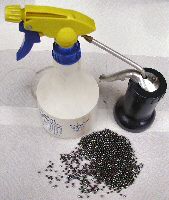 I
use lead or steel shot as ballast to keep an oil can or spray
bottle upright after being inadvertently bumped. The shot balls are large
enough so that they can't get sucked into the can or bottle's pump. If
you are worried about lead being dissolved into your oil or spry solution, or
rusting of the steel shot, then use copper plated BBs instead. In any case use
new, clean shot or wash it in acetone prior to use. I have one spray
bottle with a water-soluble oil mixture that tends to separate out after
long periods of non-use. A quick swish of the bottle, along with the agitation
caused by the shot, mixes up the solution easily.
I
use lead or steel shot as ballast to keep an oil can or spray
bottle upright after being inadvertently bumped. The shot balls are large
enough so that they can't get sucked into the can or bottle's pump. If
you are worried about lead being dissolved into your oil or spry solution, or
rusting of the steel shot, then use copper plated BBs instead. In any case use
new, clean shot or wash it in acetone prior to use. I have one spray
bottle with a water-soluble oil mixture that tends to separate out after
long periods of non-use. A quick swish of the bottle, along with the agitation
caused by the shot, mixes up the solution easily.
On another note. Most spray bottles bought at a home or garden
center will cease working after a time if oils or petroleum solvents are
used in them. The elastomer seals in their pumps just can't stand up to most
organic solvents.
I have, however, had excellent long lasting service from WD-40 spray bottles that
were purchased new and empty (see picture a right).
|
Visit Our Home Page at |
 |
Right
click below then select [Save Target As..]
From Netscape select [Save Link As..]
Microsoft
Word version of this newsletter 421 KB