Volume 2, Number 3 - March 1997
Journal of the Home Metal Shop Club of Houston, Texas. See back page for meeting information.
President - John Korman, V. Pres. - Richard Drews, Treasurer - Alan May, Secretary - J.D. Wise,
Editor - George Carlson Wk (281)376-4606, Hm (281)376-8307, Email geotek@flex.net
General News and Events
The last meeting was held on February 15th at Rutland Tool and Supply. What can I say? We had a blast. Dave Adamek and his employees did a fantastic job of hosting the meeting. About 23 people showed up. This is out of a membership of only about 30. I think that is something to be proud of. We started with a small business meeting during which a change in the way dues are calculated and collected was voted on and approved. Then Dave demonstrated many of the machines out on the floor. He told us about the machines weaknesses as well as their strong points. I think most of us lusted after that big CNC mill, about the cost of a new Mercedes. After the demos and a quick tour, Dave showed us about 6 pallets full of customer returns, broken this and that, and miscellaneous parts. Then he said he needed to get rid of it in a hurry to make room. Man, it was like flies on - oh, you get the picture. All kinds of stuff went for about a dime on the dollar, we had a great time. I doubt if there was ever a blue light special that could come close to that sale!
We all owe Dave and his employees a big thanks. John Korman has mailed a formal letter thanking Dave and Rutland Tools, if you get by there, it wouldn't hurt to say "thanks" personally.
Change In Dues Structure and Rates
At the February meeting a new method of collecting and keeping track of dues was decided on. To simplify things, all dues will have an anniversary date of September 1st. In other words, no matter when you join, the dues for the next year will be due September 1st. The dues have also been lowered to $12 per year. Dues for new members will be prorated at $1 per month, plus an $8 initiation fee. If you were to join in June, for instance, the fee would be $3 for dues plus $8 initiation, or $11. This will help make our bookkeeping much easier.
Workholding, Act 1
By George Carlson
As promised last month, I am starting a series of columns dealing with the subject of workholding.
In machine work there are only three basic operations that need to be done. They are:
-
Measuring.
- Clamping the material to be machined (workholding).
- Cutting the metal.
While all three operations have their tough points, and their own science, holding the piece to be machined can be the most trying. We will start off with simple jigs for use with the milling machine vise. As the articles progress, we will start solving more difficult situations in both the mill and the lathe.
Problem One - Machining Long Flat Things
When machining objects like instrument panels 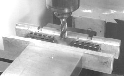 in the mill, there is always a problem supporting the work firmly and accurately. A panel may be 19" long, 3" wide, and only .062" thick. Normally you would have to clamp the panel to the table sandwiched with hardboard to protect the table. It would have to be squared up, and if you had several to do, it would take forever. The shop-made vise jaws in the photo are the answer. This is a set I have been using for quite some time. Each time I mount them in the vise, I take a very light cut to "accurize" them. The 1-2-3 blocks assure the squareness of the rear jaw. After the dressing cut is taken on the front and rear jaws, they are super accurate, in both the X and Z axis. I have used this method to machine panels where display bezels had to be chamfered very accurately. It works great.
Problem Two - Machining Slots in Long Things
 I have had to machine hundreds of rails that were used as printed circuit board guides. The slot had to be quite accurate in all dimensions so that the boards would seat properly into their connector. This is the method I used to cut the slots.
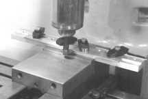
First a suitable piece of aluminum bar is placed in the vise, see the photo. A step is cut to the appropriate width and depth. A set of holes can then be drilled and tapped along the top surface for the attachment of clamps. My jig has a bunch of 3/8-16 holes and a few 1/2" through holes for good measure. Each time the jig is used, take a light dressing cut on the indexing surface. This assures very high accuracy on the positioning of the workpiece.
I have had to machine hundreds of rails that were used as printed circuit board guides. The slot had to be quite accurate in all dimensions so that the boards would seat properly into their connector. This is the method I used to cut the slots.
First a suitable piece of aluminum bar is placed in the vise, see the photo. A step is cut to the appropriate width and depth. A set of holes can then be drilled and tapped along the top surface for the attachment of clamps. My jig has a bunch of 3/8-16 holes and a few 1/2" through holes for good measure. Each time the jig is used, take a light dressing cut on the indexing surface. This assures very high accuracy on the positioning of the workpiece.
Problem Three - Making Long Parallel Things
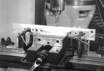 The object in the picture is a rail from a machine to program ID badges. It is 19" long, and had to be straight and parallel to about (0.001" over its length. This is how I did it. Notice the two pieces of angle clamped to the mill table. After clamping them in place, I took a light cut across the top of each one. The quill was locked during both cuts. The height of the angles is just slightly above the floor of the vise, so that when material is resting on the angles, it does not touch the bottom of the vise. This gives two perfect references for a surface in the X plane ( Y plane too for that matter). A thicker piece of material is clamped to the workpiece to reduce flex and chatter. This method works well for making parallel bars.
Problem Four - Machining the Ends of Long Bars
When I am designing electronic packaging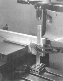 , I try to avoid requiring tapped holes in the end of rails, etc. It is not a fun thing to do if you need to be precise. One solution is shown in the photo. A piece of 1" x 4" 6061 has a step cut across its width. This should be done as accurately as possible. The solution to problem one is a good way to do this. The bar is then held on edge in a trued-up vise, and the workpiece clamped to it using the freshly milled step as reference. The 1-2-3 block provides a precision surface for the end to rest on. Note the use of the scrap piece to protect the surface of the workpiece. Don't forget to do this, aluminum can mar easily.
If you hadn't already figured it out, isn't this a much better way to do this operation rather than removing the vise and dragging out the angle plate? And truing it up, and trying to get the workpiece square, and removing the angle plate, and lifting the vise, and truing the vise, and ........
, I try to avoid requiring tapped holes in the end of rails, etc. It is not a fun thing to do if you need to be precise. One solution is shown in the photo. A piece of 1" x 4" 6061 has a step cut across its width. This should be done as accurately as possible. The solution to problem one is a good way to do this. The bar is then held on edge in a trued-up vise, and the workpiece clamped to it using the freshly milled step as reference. The 1-2-3 block provides a precision surface for the end to rest on. Note the use of the scrap piece to protect the surface of the workpiece. Don't forget to do this, aluminum can mar easily.
If you hadn't already figured it out, isn't this a much better way to do this operation rather than removing the vise and dragging out the angle plate? And truing it up, and trying to get the workpiece square, and removing the angle plate, and lifting the vise, and truing the vise, and ........
Easy Taper Turning Method
George Edwards uses this method for turning tapers between centers without having to change the offset of his tailstock.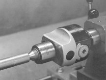 The trick is to use a normal boring head with a couple of changes. The normal R8 arbor is replaced with a Morse taper arbor to fit the hole in the tailstock spindle. These arbors are available from suppliers, or you can make your own. If you buy one, you may have to saw off the tang on the arbor. This is to allow the boring head to be set level in the tailstock.
The other item is the live center. Find a live center that does not have a spindle inside the shank. The solid shank is required because the shank must be cut short to fit into the boring head. George found a solid shank version with a straight-sided shank. It would not be difficult to turn a shank down if necessary.
As you can see in the photo, offsetting the center is as simple as turning the adjustment on the boring head. Precision moves can be made using the scale on the adjustment screw.
Lathe Helpers
By John Korman
CHUCK BLOCK FOR LATHE
To prevent chuck dropping on ways of lathe and to hold square with spindle, a block as shown will prevent busted knuckles, dented ways, and make it easier to align chuck when mounting chuck to spindle. When loosing or tightening the chuck NEVER strike or use the chuck body. Rather grip the hub of back plate. An ideal wrench is a plumbers strap wrench or a spanner wrench. Make one if you don't have one.
TOOL TRAY FOR LATHE
It is not necessary to pile work, tools, and other things on the lathe bed and carriage. A tool board will keep these things at the foot of the bed and keep them handy, prevent cluttering the ways and carriage. The board should have raised sides to prevent tools, etc. from falling off. If more room is needed; a double deck can be added.
Desperate Men Do Desperate Things
By George Carlson
After being frustrated by the cheap stand that came with my cutoff saw, I've decided to do something about it. It has only taken 12 years, but I have now constructed a new stand for the saw. The stand supports a coolant tray on which the saw is attached. Making the coolant tray is the tough part. I did not have a brake that was capable of bending the 14-gauge sheet metal, so I cut a sixty-degree groove halfway through the material where the fold was needed. The best way to do this would have been to use a sixty-degree double-angle cutter with the mill set-up as a horizontal mill. The cutter would have to be at least 4" in diameter for this to work. T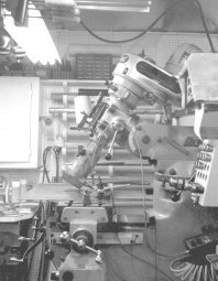 hat would be a very expensive cutter. Instead, I had to set-up my mill in a rather strange way in order to do this. As shown in the photo, the head had to be tilted back thirty degrees, and the right angle adapter attached. A sixty-degree dovetail cutter would have worked well, except I didn't have one. I used a 3/4" shank cemented carbide boring bar with the tip ground to sixty degrees. It became a homemade single flute dovetail cutter. Using this arrangement, I was able to cut the four grooves very precisely. The corners were notched at the appropriate angle, and the tray was folded using a bench vise, some angle iron, and a couple of C-clamps.
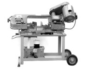 The result is shown in the photo. Note that the handle on the left side of the photo can be withdrawn from the base to make the saw easier to move. All that is left to do is make a coolant nozzle and wire up the coolant pump.
I will publish the complete plans in the next issue of the newsletter. There must be thousands of saws similar to this one, that are in need of a nice stand.
The result is shown in the photo. Note that the handle on the left side of the photo can be withdrawn from the base to make the saw easier to move. All that is left to do is make a coolant nozzle and wire up the coolant pump.
I will publish the complete plans in the next issue of the newsletter. There must be thousands of saws similar to this one, that are in need of a nice stand.
Chart of Dimensions of Common Screws
This chart is in Adobe PDF format. It is a handy guide for design using various screws from niumber 0 through 1". Download this file and print it out using the Adobe Acrobat reader.
Download Chart (22K)
