Volume 8, No 5 - May, 2003
|
|
Volume 8, No 5 - May, 2003 |
|
|
|
|
|
| President - |
Vice President - |
||
| Treasurer - |
Secretary - |
||
| Webmaster - |
Editors - |
||
| Founder - |
SIG Coordinator - |
Statement of Purpose
Membership is open to all those interested in machining metal and tinkering with machines. The club provides a forum for the exchanging of ideas and information. This includes, to a large degree, education in the art of machine tools and practices. Our web site endeavors to bring into the public domain written information that the hobbyist can understand and use. This makes an organization such as this even more important.Regular Meeting
 Collier Library, 6200 Pinemont, Houston, Texas, April
12, 2003, 1:00 pm. Tom Moore, President, presiding. There were 33 attendees
with four visitors, Jeff Applebee, Leo Reed, Dale Jones, and John Slather.
A get well card for John Robb was signed by all present. Alan May asked about
starting a group for beginners. He got a lot of interest from those present.
Collier Library, 6200 Pinemont, Houston, Texas, April
12, 2003, 1:00 pm. Tom Moore, President, presiding. There were 33 attendees
with four visitors, Jeff Applebee, Leo Reed, Dale Jones, and John Slather.
A get well card for John Robb was signed by all present. Alan May asked about
starting a group for beginners. He got a lot of interest from those present.
Business Meeting
Minutes are sent via email or regular mail to club members.
Presentation
Hardening of steel by heat treating and cold working
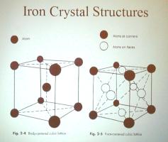

Our speaker Dr. John Slather, a metallurgist with Invatech Corp., spoke about hardening of steel by heat treating and cold working. He explained tempering and annealing. In a nut shell, heat carbon steel to a redness where it loses its magnetism. Hold at temperature for a minute or so with longer time for larger mass. Quench in salt water. Withdraw, allowing the surface to reheat from internal heat. Quench again till cool.
.Show and Tell
|
Dean Eicher showed a roll pin extractor he made from a C-clamp. |
Gordon Lawson talked about de-scaling iron with acid |
Vincent D'Amico showed a photocopy stand he made for use in his library research work |
|
Joe Scott showed an ancient, pre 1930's, auto crankshaft scraper |
Leo Reed showed a boring head that he machined on a drill press using an X-Y table |
Not Pictured:
Joe Williams showed a still working, heat damaged calculator and digital caliper that resulted from his recent shop fire.
Dick Kostelnicek brought a store bought adaptor for his Yankee screwdriver that adapts it to current style 1/4-in. hex insert bits.
Tom Moore showed paint stick crayons used to rub into metal stampings and engravings to make the impression stand out.
 The
Casting Special Interest Group had a meeting after the regular session. The
frogs from the casting session at Zube were reviewed. The castings came out very
good, with one showing some unusual coloration and some excessive pitting on the
sides. This was possibly due to the use of scrap without adding any flux or
doing any degassing.
The
Casting Special Interest Group had a meeting after the regular session. The
frogs from the casting session at Zube were reviewed. The castings came out very
good, with one showing some unusual coloration and some excessive pitting on the
sides. This was possibly due to the use of scrap without adding any flux or
doing any degassing.
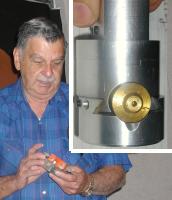
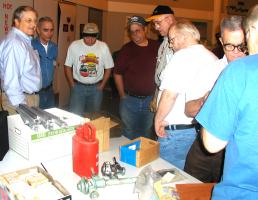
Zube Park Frog Pour
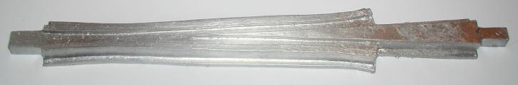
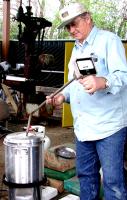
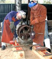 At the left is Dennis Cranston checking the furnace temperature. At
the right Ed Gladkowski and Ray Etheridge are making a dual pour
order to ensure
there is enough metal to fill the mold. The workshop yielded four frogs for the Houston Area Live Steamers train track. We also got a chance
to try out our new molding bench. by Dennis Cranston - SIG Coordinator
At the left is Dennis Cranston checking the furnace temperature. At
the right Ed Gladkowski and Ray Etheridge are making a dual pour
order to ensure
there is enough metal to fill the mold. The workshop yielded four frogs for the Houston Area Live Steamers train track. We also got a chance
to try out our new molding bench. by Dennis Cranston - SIG Coordinator
Computer Numerical Control SIG
No activity this Month. The homebrew CNC SIG will meet next time. Jan Rowland will have some handouts on controlling equipment directly by using Basic on the PC. Bring anything for the CNC SIG show and tell.
Featured Articles
Drill
Press Modification
by J. R. Williams - HMSC Member
The small drill press seemed like a good buy at the time, but I hesitate to think about the time spent in making it a viable tool. I have a 20-in. Clausing drill press, with a #3 taper shank spindle that handles the heavy hauling, but this little unit does make a lot of chips.
 The
drill press started out as a low cost import from Home Depot many years ago
and its design problems quickly became apparent. The first item was the column
length, as it was not possible to use a drill press vise and a standard length
jobber drill bit. The column, 1.850-in. dia., was extended 7 inches by
machining a matching tube with a plug that was pressed into both the extension
and the original column. The depth stop unit was a plastic collar around the
quill lower end and was very flexible. So, a new one was fabricated from a section
of 1/4-in. plate stock. The original drive motor (1/5-hp) was first replaced
with a 1/4-hp unit. When a DC motor became available, it was replaced. The DC
motor from a treadmill was going to the scrap yard. It had
a loose field magnet that was repaired with Epoxy, and a new outboard bearing
was installed. The motor was powered with a Variac� and a DC bridge rectifier
until a control unit became available at a Club Swap Meet. This led to
changing the unit's pulleys and belt with new aluminum pulleys and a multi-groove
automotive belt. Both pulleys are 3-3/4 in. OD. I have plans to change the
drive pulley to one in the 1-1/2 in. range. The quill does not have sufficient
bearings nor a tight drive spline to handle the high speed that is available. The
motor base plate mount was replaced to fit the second motor and revised again
for the DC drive. The belt guard went the way of many plastic items in
my recent shop fire and a new one needs to be fabricated. A Teflon washer
was added to the quill return spring unit to prevent binding.
The
drill press started out as a low cost import from Home Depot many years ago
and its design problems quickly became apparent. The first item was the column
length, as it was not possible to use a drill press vise and a standard length
jobber drill bit. The column, 1.850-in. dia., was extended 7 inches by
machining a matching tube with a plug that was pressed into both the extension
and the original column. The depth stop unit was a plastic collar around the
quill lower end and was very flexible. So, a new one was fabricated from a section
of 1/4-in. plate stock. The original drive motor (1/5-hp) was first replaced
with a 1/4-hp unit. When a DC motor became available, it was replaced. The DC
motor from a treadmill was going to the scrap yard. It had
a loose field magnet that was repaired with Epoxy, and a new outboard bearing
was installed. The motor was powered with a Variac� and a DC bridge rectifier
until a control unit became available at a Club Swap Meet. This led to
changing the unit's pulleys and belt with new aluminum pulleys and a multi-groove
automotive belt. Both pulleys are 3-3/4 in. OD. I have plans to change the
drive pulley to one in the 1-1/2 in. range. The quill does not have sufficient
bearings nor a tight drive spline to handle the high speed that is available. The
motor base plate mount was replaced to fit the second motor and revised again
for the DC drive. The belt guard went the way of many plastic items in
my recent shop fire and a new one needs to be fabricated. A Teflon washer
was added to the quill return spring unit to prevent binding.
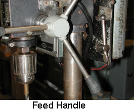
 The
feed handle presented a problem of keeping the handles tight, so a new
hub was machined and the problem was solved with deeper threads. Shown in the right
side view is a sheet metal hanger for the chuck key that has a steel ball silvered
on the end of the handle. The chuck was replaced with a Jacobs� 1/2-in.
unit. The original chuck was discarded. It would not close on small
drill bits and had a lot of run out. The process required a little machine work on
the taper end of the shaft.
The
feed handle presented a problem of keeping the handles tight, so a new
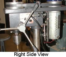
hub was machined and the problem was solved with deeper threads. Shown in the right
side view is a sheet metal hanger for the chuck key that has a steel ball silvered
on the end of the handle. The chuck was replaced with a Jacobs� 1/2-in.
unit. The original chuck was discarded. It would not close on small
drill bits and had a lot of run out. The process required a little machine work on
the taper end of the shaft.
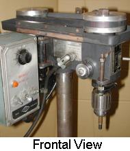
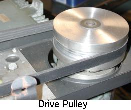
The drive pulleys were machined from aluminum bar stock and have flat bottoms with side contact on the belt. The matching grooves are not necessary in this low power use. In the photo you can see a sheet metal insert that was added to the belt guard to keep it in place and stop a rattle.
The right side view shows the unit with the belt pulleys needing alignment, the chuck key hanger and the modified handles.
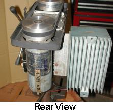
 The
rear view shows the motor and the rear of the drive unit with a simple
right angle mounting bracket for the cast housing of the DC motor drive unit.
The
rear view shows the motor and the rear of the drive unit with a simple
right angle mounting bracket for the cast housing of the DC motor drive unit.
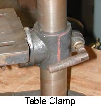
The table clamp screw of the original unit was marginal in size and ease
of use, so a 3/8-in. SHCS (socket head cap screw) was modified to use the original
clamp handle and was fastened with silver solder. The next problem
soon became apparent. The table was not square to the column! The
table bracket was removed and the base section was squared up in the mill. A
taper pin installed to keep the table from rotating.
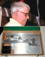
Small Hand Tapping Guide
by
Dick Kostelnicek - HMSC Member
 Keeping
a small tap running straight while gingerly applying just the right amount
of torque
is only learned after breaking off a number of taps in a workpiece that
you've spent days crafting. You must experience this frustrating aspect of machine
work, for no amount of advice nor warnings will do any good at all.
Keeping
a small tap running straight while gingerly applying just the right amount
of torque
is only learned after breaking off a number of taps in a workpiece that
you've spent days crafting. You must experience this frustrating aspect of machine
work, for no amount of advice nor warnings will do any good at all.
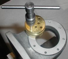
Well, after you've paid your tap-breaking dues, you'll be able to appreciate this age old idea, the small hand tap guide. Now, I have one of those fancy tap jig-guides bolted to my work bench that requires you to bring the work over to it. But this simple guide goes to the work, a distinct advantage when you may not want to knock down your setup on a machine.
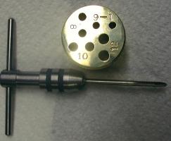
It is 1-1/2 in. dia. by 1 in. high, made from brass, and has a raised knurled grip ring (diameter each side of knurl is turned down). The guide holes for each size tap are a bit larger than the normal body or through hole for that screw thread. Not for clearance reasons, but because the standard shank diameter of a tap is a bit larger than the major diameter of the screw thread. This oversize guide hole allows a tap loaded with chips to be easily withdrawn from the guide. My version of the guide covers #1 through #12 taps. Two identical holes for each shank diameter are located at radii of 0.25 and 0.5 in. These two hole offsets allow me to get into tight corners or up against a shoulder while still enjoying the stability of the full base diameter when using the hole closest to the guide's center.
|
|
Tap # |
# Drill |
When you make yours, first drill the holes about 10% undersize! Then ream to final diameter with the correct size drill. Remember,
drills drill oversize, never undersize. The table shows drill sizes for shank diameters
of the numbered screw taps.
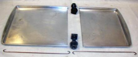
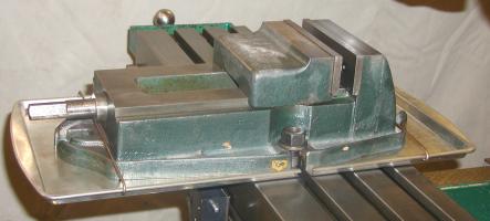
Milling Vise
Drip Pan
by Dick Kostelnicek - HMSC Member
|
|
|
|
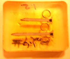
Using a milling vise together with flood cooling was always a messy affair until I started using a drip pan. My vise, a 6-in. Palmgren, has its own drip catching edge cast right into the base. However, the discharged spillways are at the extreme front and back of the vise. For most setups, this is precisely the worst location. The fluid runs right on to the floor rather than into the mill table T-slots, where it could easily be collected. I tried hanging small buckets under the for and aft spillways, but one or two inadvertent bumps to a pail while working around the machine put an end to that fluid collecting technique.
To the rescue.... One day my wife stopped by the shop and said, "I'm throwing out these old metal serving trays. Do you want them?" Well, the pictures at the left show the result. I removed the paint and cut (friction sawed) the trays so that they formed a drip pan under my mill vise. The tray thickness is 0.012-in. and they are made from some non-rusting or plated metal. The two pans slip completely under the vise right up to the hold down bolts. The overhanging pans are supported by wire bails that slip over the vise spillways. The bails are made from 1/8-in. gas welding rod with J- looped ends that hook under the pan lips.
Now, the flood coolant runs right into the table
T-slot in which the vise hold-down bolts are secured.
|
The next meeting will be held on Saturday May 10, 2003 at the Collier Library 6200 Pinemont, Houston, TX at 1:00 p.m. Bring along a work in progress to show. Visit Our Web Site |
 |
Right click below then select [Save
Target As...]
From Netscape select [Save Link As..]
Microsoft
Word version of this newsletter 286 KB