Volume 7, No 11 - November, 2002
|
|
Volume 7, No 11 - November, 2002 |
|
|
|
|
|
| President - |
Vice President - |
||
| Treasurer - |
Secretary - |
||
| Webmaster - |
Editors - |
||
|
|
|
SIG Coordinator - |
Statement of Purpose
Membership is open to all those interested in machining metal and tinkering with machines. The club provides a forum for the exchanging of ideas and information. This includes, to a large degree, education in the art of machine tools and practices. Our web site endeavors to bring into the public domain written information that the hobbyist can understand and use. This makes an organization such as this even more important.Business Meeting
Minutes are sent via email or regular mail to club members.
Regular Meeting
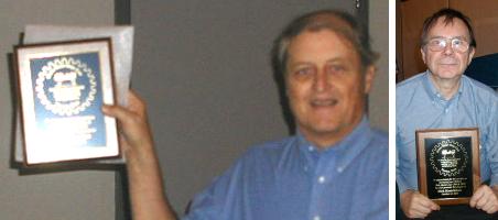
Dennis Cranston - Dick Kostelnicek |
Presentation
 Our
program consisted of two videos on TIG (Tungsten Inert Gas) welding that
were provided by Chuck West, member HMSC. Chuck is taking welding
classes at a local junior college. The videos explained which polarity
to use on various metals.
Our
program consisted of two videos on TIG (Tungsten Inert Gas) welding that
were provided by Chuck West, member HMSC. Chuck is taking welding
classes at a local junior college. The videos explained which polarity
to use on various metals.
The discussion concerned auto-darkening welding hoods. The consensus was
that they work well with the costlier ones having faster light-to-dark transition times.
A discussion on general welding experience and tips followed.
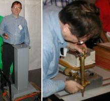
Show and Tell
Joe Williams showed a corner finder, a B&S center finder and some 1-1/4-in. wide rubber belting he has available. |
Ray Ethridge showed how he repaired a bandsaw wheel support by fabricating a spindle bushing from his own ZA12 casting. He also brought a homemade expanding mandrel to hold an odd-sized part. |
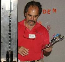
Bill Swan demonstrated the power of a stepper motor by twisting a piece of key stock. |
Dick Kostelnicek showed his weldment grinder stand that was smoothed with Bondo, sanded and painted. It looks like a fine casting. He demonstrated his home built flame cutting tractor and track, how to cut empty 1-gal. solvent cans to make storage drawers, and a lathe ball turning attachment. |
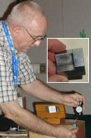
Joseph Scott brought an old centering device for face plate work and a holder for drilling in the lathe. He also showed a punch set for making a M1 rifle sight screw seal. |
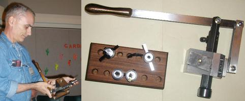
Ed Gladkowski showed his home built lever actuated shaper that mounts on a lathe in place of the toolpost. One use is cutting key ways in work held at the headstock. |
 Tom Moore discussed the plans for a club foundry at Zube Park. It was decided
that when we had a tailgate sale there, we would get together afterwards and
work on a molding bench and other items. Ed Gladkowski showed the special flask
he used to cast a handle for his lathe attachment. In this flask, he cast a hand-hold
piece in silicon bronze directly on a metal bar (see Show & Tell). by
Dennis Cranston
Tom Moore discussed the plans for a club foundry at Zube Park. It was decided
that when we had a tailgate sale there, we would get together afterwards and
work on a molding bench and other items. Ed Gladkowski showed the special flask
he used to cast a handle for his lathe attachment. In this flask, he cast a hand-hold
piece in silicon bronze directly on a metal bar (see Show & Tell). by
Dennis Cranston
Computer Numerical Control SIG
No activity this Month.
Featured Articles
Lathe Spindle Outrigger Support
by Dick Kostelnicek - HMSC Member
Turning
an unsupported slender rod, that extends far beyond the backside of the
spindle, represents a serious danger to both equipment and lathe operator. For
a given diameter, length, and rod stiffness, there is a rotational speed
above which the rod is unstable. As the unsupported end is thrown off-center,
centrifugal force drives it further off-center. 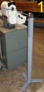 The result, a catastrophic whipping
of the rod as it bends ninety degrees to the spindle slashing everything traverse
to the lathe axis.
The result, a catastrophic whipping
of the rod as it bends ninety degrees to the spindle slashing everything traverse
to the lathe axis. 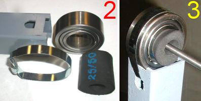 Although I was always cautious of this possibility,
recently, a 3/8-in. dia. 3-ft. long drill rod got away from me at about 400 RPM..
It did quite a bit of damage to a swing-out tool tray attached to the back of
the head
stock casting. I resolved to ensure that this not happen again.
Although I was always cautious of this possibility,
recently, a 3/8-in. dia. 3-ft. long drill rod got away from me at about 400 RPM..
It did quite a bit of damage to a swing-out tool tray attached to the back of
the head
stock casting. I resolved to ensure that this not happen again.
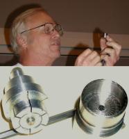
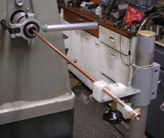
Figure 1 shows my solution for supporting slender rods by using a spindle outrigger. It is built from a light weight, three legged, grinder pedestal (Harbor Freight #42986) supporting a telescoping length of 2 x 2-in. square tubing. Fortunately, the square tube fits closely within the pedestal pipe. Attached to the end of the square tube is a roller bearing with a 1-3/8-in. dia. bore, larger than the through-hole in my lathe's spindle.
Figure 2 shows a short length of black, low density, rubber tubing, commonly used as insulation over refrigeration lines, that serves as a compliant centralizer. The rubber tube is stuffed inside the bearing's bore and compresses enough to accommodate rods between 1/4 and 3/4 in. dia. Used without the rubber centralizer, the outrigger is built stout enough to also serve as a dead weight support for large diameter, long rods.
The parts for attaching the bearing to the end of the square tubing are shown in figure 2. Notches were filed in the square tube's end to seat the bearing. A cross drilled 5/8 in. dia. hole had its top-side filed flat to accommodate a band clamp that ties the bearing to the tube as seen in figure 3.
 Figure
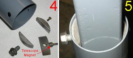
4 shows the parts that allow height adjustment and clamping
of the pedestal's round pipe to the square extension tube. Two sets
of new-moon shaped shims were cut from key stock and
rounded on a belt sander. The left
shim has a 3/8-16 threaded through-hole while the one on the right was tapped
for a #10-32 screw. Figure 5 shows that the left shim provides sufficient
thread engagement for the 3/8-in. bolt that couldn't be obtained within the thin wall of the pedestal
pipe. The right shim is screwed down tight
to the opposite side of the pipe. Tightening the 3/8-in. bolt cinches the square tube between
the bolt's end and the opposed fixed shim.
Figure
4 shows the parts that allow height adjustment and clamping
of the pedestal's round pipe to the square extension tube. Two sets
of new-moon shaped shims were cut from key stock and
rounded on a belt sander. The left
shim has a 3/8-16 threaded through-hole while the one on the right was tapped
for a #10-32 screw. Figure 5 shows that the left shim provides sufficient
thread engagement for the 3/8-in. bolt that couldn't be obtained within the thin wall of the pedestal
pipe. The right shim is screwed down tight
to the opposite side of the pipe. Tightening the 3/8-in. bolt cinches the square tube between
the bolt's end and the opposed fixed shim.
A second set of shims is located halfway down the pedestal
pipe. In the lower right corner of figure 4, a ceramic magnet, attached to a
telescoping handle, is shown stuck to a shim. The telescope magnet was the prefect tool for locating the
lower set of shims deep within the pedestal pipe.
External
Spindle Support
by J.
R. (Joe) Williams - HMSC Member
 I suspect almost everyone has had a part bend when unsupported. Mine
cost
me a good work lamp on my old milling machine. The half inch stainless steel
bar formed a nice 90-degree radius bend, and in a hurry, at 770-rpm, the speed I usually use. It sure gets your attention. My solution
is shown in the photo. It is built around a section of cadmium plated
1-1/4-in. steel pipe attached to a couple of round heavy steel drops and has a
vertically adjustable shelf at the top. The heavy round base makes it easy
to roll around to get it out of my way when not in use. The work is usually
supported thru a drilled hole in a piece of high density polyethylene or simply
a piece of wood. The work in the photo is a section of heavy wall 3/8-
in. copper tube with a special fitting on the end.
I suspect almost everyone has had a part bend when unsupported. Mine
cost
me a good work lamp on my old milling machine. The half inch stainless steel
bar formed a nice 90-degree radius bend, and in a hurry, at 770-rpm, the speed I usually use. It sure gets your attention. My solution
is shown in the photo. It is built around a section of cadmium plated
1-1/4-in. steel pipe attached to a couple of round heavy steel drops and has a
vertically adjustable shelf at the top. The heavy round base makes it easy
to roll around to get it out of my way when not in use. The work is usually
supported thru a drilled hole in a piece of high density polyethylene or simply
a piece of wood. The work in the photo is a section of heavy wall 3/8-
in. copper tube with a special fitting on the end.
Welding
Table
by J.
R. (Joe) Williams - HMSC Member
 The welding table in figure 1 is constructed from sheet metal angles that are
riveted together, a good exercise in riveting. The top surface is made from
six 12 x 12 x 2-in. fire bricks set in a pan top with a heavy steel angle section
on the right side and a section of steel angle set to form a V for
positioning round parts. The old Post Vise (antique blacksmith's vise)
was added later. The table is about 39-in. tall and built to provide
space underneath for my welding machine. On the right side are two
projections for storage of a short welding lead and ground cable. All the
metal surfaces including the vise and the bench top are bonded together with
welding cable to provide a ground for the work.
The welding table in figure 1 is constructed from sheet metal angles that are
riveted together, a good exercise in riveting. The top surface is made from
six 12 x 12 x 2-in. fire bricks set in a pan top with a heavy steel angle section
on the right side and a section of steel angle set to form a V for
positioning round parts. The old Post Vise (antique blacksmith's vise)
was added later. The table is about 39-in. tall and built to provide
space underneath for my welding machine. On the right side are two
projections for storage of a short welding lead and ground cable. All the
metal surfaces including the vise and the bench top are bonded together with
welding cable to provide a ground for the work.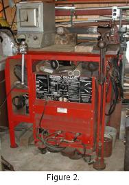 The welding machine sits on a caster base, figure 2, and is
fabricated
from welded 1/4 x 4-in. flat steel. This allows the machine to be close to the
floor and rolled around. Otherwise, a fork truck would be required.
The welding machine sits on a caster base, figure 2, and is
fabricated
from welded 1/4 x 4-in. flat steel. This allows the machine to be close to the
floor and rolled around. Otherwise, a fork truck would be required.
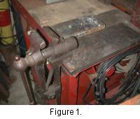
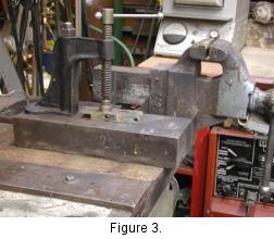 Figure 3 shows another welding station with a large steel bench block
that
has a screw clamp bolted to the top. The block is loose and can
be moved
around and fastened with additional C-clamps to the front ledge of the work bench. The clamp body came from a scrap pile minus the Acme screw
and pad. The
block has a ground wire attached at the rear to a common ground system that
eliminates the problem of attaching a ground lead for stick or TIG
welding.
Figure 3 shows another welding station with a large steel bench block
that
has a screw clamp bolted to the top. The block is loose and can
be moved
around and fastened with additional C-clamps to the front ledge of the work bench. The clamp body came from a scrap pile minus the Acme screw
and pad. The
block has a ground wire attached at the rear to a common ground system that
eliminates the problem of attaching a ground lead for stick or TIG
welding.
My gas welding equipment, cylinders, including Argon, and hose
are not shown. They sit to the left of the welding bench. A small heat
treating oven, figure 3, is parked on the left side of the welding
bench.
Another Welding Table
by Dick Kostelnicek - HMSC Member
 Figure
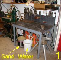
1. shows my welding table. It is constructed from 3/16-in. welded mild steel
plate and 2-in. dia. pipe legs. It has a metal back-splash
that is lag bolted into the wall studs. Hence, the table does not
move when leaned or pushed upon. The legs screw into straight threaded pipe
couplings welded to the table. The working surface is leveled by adjusting the
amount of each leg's thread engagement. The backsplash and top are bare metal, while the
underside and legs are painted. The top overhangs the apron at the front
and sides
so
that C-clamps or vice-grips can be used to secure work to the table
top. I store my vice-grips and C-clamps by clamping them around the edge of
the backsplash
for easy availability.
Figure
1. shows my welding table. It is constructed from 3/16-in. welded mild steel
plate and 2-in. dia. pipe legs. It has a metal back-splash
that is lag bolted into the wall studs. Hence, the table does not
move when leaned or pushed upon. The legs screw into straight threaded pipe
couplings welded to the table. The working surface is leveled by adjusting the
amount of each leg's thread engagement. The backsplash and top are bare metal, while the
underside and legs are painted. The top overhangs the apron at the front
and sides
so
that C-clamps or vice-grips can be used to secure work to the table
top. I store my vice-grips and C-clamps by clamping them around the edge of
the backsplash
for easy availability.
Note the sand and water buckets under the table. I use sand as an amorphous fire brick. When poured in a pile on the table, it positions and supports odd shaped work pieces, prevents splatter from sticking to the table, covers hot welds so they cool slowly, and smothers the occasional fire. Water is used for quenching hot metal and to put out fires. Gas cylinders and hoses are located to the left of the table. Flux, rod, and solder are stored in the two pull-out drawers immediately above the table. Hoods, groves, and various welding jigs and fixtures are stored on three 12-in. deep open shelves attached to the wall above the pull-out drawers
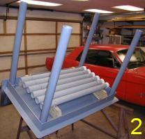
 After
construction and painting, several 2-in x 32-in. long. PVC tubes were suspended under the
table, figure 2. These tubes hold a variety of gas welding and brazing
rods. As shown in figure 4, the left most tubes are a convenient place to hold
my pneumatic needle descaler and chipper chisel.
After
construction and painting, several 2-in x 32-in. long. PVC tubes were suspended under the
table, figure 2. These tubes hold a variety of gas welding and brazing
rods. As shown in figure 4, the left most tubes are a convenient place to hold
my pneumatic needle descaler and chipper chisel.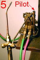
Figure 5 shows a gas-saver shut off device that is used to turn the torch on and off. When the weight of the torch pulls down on the hanger arm, the gas shuts off. When welding gases are present, the device has an acetylene pilot that burns continuously. By simply picking up the torch and passing it over the pilot, the torch ignites. The advantage is that the torch may be put down, shut off, and then re-ignited without ever adjusting the torch valves. The gas-saver is attached to a large ceramic magnet so that it can be stuck to any available metal surface.
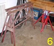 On
the other side of the shop, as seen in figure 6, are the welding machine and
various work supports. 35-ft. of welding cable is shown hanging
behind the two metal support horses. I weld large items in the center of
the shop, where there is a ceiling hoist, or out-of-doors. The long cables are
quite necessary. When I
use the table for electric welding, I run the cables across 15-ft.
of shop floor and clip the ground cable to the
edge of the welding table
On
the other side of the shop, as seen in figure 6, are the welding machine and
various work supports. 35-ft. of welding cable is shown hanging
behind the two metal support horses. I weld large items in the center of
the shop, where there is a ceiling hoist, or out-of-doors. The long cables are
quite necessary. When I
use the table for electric welding, I run the cables across 15-ft.
of shop floor and clip the ground cable to the
edge of the welding table
|
Table Dimensions (inches) |
|
|
Top |
45 x 27 |
|
The next meeting will be held on Saturday November 9, 2002 at the Collier Library 6200 Pinemont, Houston, TX at 1:00 p.m. Bring along a work in progress to show. Visit Our Web Site |
 |
Right click below then select [Save
Target As...]
From Netscape select [Save Link As..]
Microsoft
Word version of this newsletter 288 KB