Volume 1, Number 7 - November 1996
Journal of the Home Metal Shop Club of Houston, Texas. See back page for meeting information.
President - John Korman, V. Pres. Richard Drews, Treasurer - Alan May, Secretary - J.D. Wise
Editor - George Carlson Wk 376-4606, Hm 376-8307, Email geotek@flex.net
General News and Events
The last meeting was held on October 19th at the library. John Korman was unable to attend, so Alan May officiated. We had several new visitors with us, we hope they will return for the meeting on the 16th of this month. George Carlson brought in a few photographs of foundry work done by Paul Gennusa while he was a student at Lamar University. Paul has designed several small cupola type furnaces for the production of cast iron. Paul is pretty busy as manager of Film Depot, but he always likes to talk about his experience with small scale foundry work. He can be reached at 580-1667.
Of Special Interest or "This Journal Needs Some Lube"
As always, we are desperately needing original articles to publish in this Journal. ( I am running out of ideas.) Please do not submit articles that have been published elsewhere unless you own the copyright. If you would like to submit an article, idea, or photograph there are several ways this can be done. The best way to submit an article is in machine readable form. A plain text file is the easiest to work with. It can be placed on a floppy and mailed to my home, or, attached to an Email and sent via the Internet. Articles and other ideas can also be faxed to my office at (713) 251-3860. This is a Spring number, and will be a toll call for most of you. If you have any photographs of projects, I would like to try to publish them here. If you have a scanner, send me the scanned image file in JPG or TIFF format over the Internet or via US mail. If you don't have a scanner, send the photo in the mail, or hand it to me at a meeting. I don't think the FAX will work well enough. If you don't have a usable photo of your project, give me a call and we'll shoot it on 4x5 Polaroid and make it look pretty. Also, mechanical drawings in DXF, WMF, CGM, or AutoCAD DWG are easy to put into the newsletter.
Membership Information
Membership is open to all those interested in machining metal and tinkering with machines. We currently have members that have considerable backgrounds in the hobby, and other members that are just starting. The purpose of the club is to provide a forum for the exchanging of ideas and information. This includes, to a large degree, education in the art of machine tools and practices. There is a severe shortage of written information that a beginning hobbyist can use. This makes an organization such as this even more important. Please send in your dues to help keep this club in sound financial shape and continue to help more people get into this fascinating hobby. For membership information and forms, call John Korman at (713) 723-8597.
Gears
As I cautioned last month, this month's feature will be the subject of gears and gear making. In one of Guy Lautard's Bedside Readers there was a story of a fellow that worked at a machine shop where various jobs were done, including gear cutting. He was on the shipping dock one day packing up a few gears they had made, readying them for shipment to the customer. The UPS guy showed up and asked the machinist about the gears. The machinist explained that they made the gears there in the shop. The UPS man replied "I didn't know you could make gears, I thought you had to buy them."
I promise I will not get too deep in the theory of how gears operate, the geometry can be very complex, and I don't really understand it all that well myself. There are numerous books and articles available on the subject of gearing. The "Machinery's Handbook" is a good place to start. I have a book called "Gear Wheels & Gear Cutting" by Alfred W. Marshall. It is an English publication from Model and Allied Publications, Ltd. My copy was printed in 1968, but I'm sure it is still available through Tee Publications. They are on the Internet at "http://www.fotec.co.uk/mehs/tee.index.html". What we will cover is a little information on gear design, and enough information on gear cutting to get you started on your next "Big Ben".
Gear mechanisms have been around since ancient times. Geared devices have been used for everything from watering horses to computing complex trajectories for artillery shells. We will be limiting our discussion here to common spur gears, this is the type of gear you would find in clocks, transmissions, and lathes. Cutting gears that operate smoothly and reliably require a good deal of precision work. Not only do the teeth have to be spaced accurately, but the form of the tooth is very important. This is because well made gears roll over one another, the surfaces do not slide. Also, even though the contact area of the gears is moving and changing distance from the center of the gear as teeth come together and separate, the angular velocity of the driven gear remains constant. This is no small feat. The key to all this is a shape called the Involute Curve. Since this shape changes as the diameter of the gear changes, it makes cutting various sizes of gears a little more challenging.
Methods of Generating Gears
As written above, the shape of gear teeth can be quite complex. So how can gears be made so cheaply? Engineers have devised several methods to cut gear teeth and generate the required tooth profile at the same time. The simplest way to do this is to use a rack as a broaching tool. Since the rack is straight, there are no complex curves to cut, only teeth that are trapezoid in shape. The angle of the side of the trapezoid is generally 141/2(, the same as an acme thread ( included angle 29( ). The space between the teeth are the same size as the teeth. ( Two racks placed face to face would fit together perfectly) The trapezoid shape will prevent the generation of gears where the tooth becomes undercut ( especially in the case of small diameters ). This rack is then used as a broach cutting the teeth into the gear blank. The blank is turned between cuts, 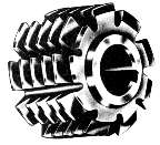 and the rack is moved the same distance. After several passes, the teeth are cut to full depth, and the correct shape is also generated. This is essentially how a gear hob works. Instead of a rack, the hob looks like a very large tap. The teeth on the hob have the same shape as the teeth on the rack, they are simply "wrapped" around the hob. This make the gear generation a continuous process, where the gear blank is rotated while the rotating hob is fed into it. Using this method, any size spur gear, ( of the same series ), can be made with the same tool. Obviously, this requires much more sophisticated equipment then what you find in the average small shop.
Cutting Tools for the Small Shop
In the small shop, we need to keep things simple, so toolmaker's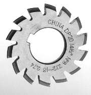 have devised a system of gear cutters that can cut good quality gears on normal shop tools such as a dividing head and a mill. A photograph of a gear cutter is shown on the right. Since, as stated earlier, gear teeth vary in profile as the number of teeth on a gear are changed, one cutter cannot be used for cutting all diameters of gears. The cutters come in sets of eight. As you can see in the photo at the lower right, there is quite a difference in the profile of the #1 cutter on the right, compared to the #8 cutter on the left. Unfortunately, gear cutters are not cheap. A full set of eight will run between $90 and $240, depending on where you can find them. If only a few gears need to be made, and you have a gear to use as a pattern, you can make a fly cutter to do the job.
 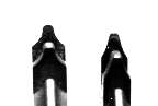 The picture at the left
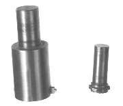 has a fly cutter I made to cut a metric gear for a Grizzly 9x19 lathe I had. The lathe did not have a toggle gear for cutting left hand threads, so I made one. I traced the profile of a gear of the same size that was already part of the train on a HSS blank and carefully ground it out. It worked great. The other homemade cutter was made to make a threading indicator for a friend's 10" Logan. I made the cutter to have the same profile as the lead screw, and used it to machine a bronze gear for the indicator. Still working fine.
The Dividing Head
The key to making accurate gears is the dividing head. This can be a commercial unit as shown at the right,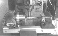 of a shop built device using various gears and plates as a reference. I mounted my dividing head on a sturdy aluminum rail. This allows me to pull the unit out of the cabinet and put it in the milling vise very quickly. The headstock and tailstock are always in alignment. I also mounted a small chuck on the head and this comes in very handy. The dividing head uses a worm gear arrangement that produces a 40:1 ratio. It requires forty turns on the handle to rotate the head through 360 degrees. There are 24 holes in the plate mounted on the main spindle for use in dividing 2, 3, 4, 6, 8, and 12 places. The plates on the side of the head are also used to divide the
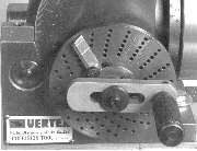 rotation of the handle into various amounts. Three plates are provided with hole counts of 15, 16, 17, 18, 19, 20, 21, 23, 27, 29, 31, 33, 37, 39, 41, 43, 47, and 49. Sector arms make it easy to move a set number of holes and not lose count. All numbers from 1 to 50 can be done, and many more beyond. To cut a gear of say 29 teeth, do the following: Divide 40 by 29, this gives 1and 11/29's. Use the 29 hole plate, set the sector arms so that when one arm is placed against the pin of the handle, the other arm just uncovers the hole, 11 holes away. For each space, make sure the sector arm is placed against the pin, rotate the handle one turn and 11 holes, to the other sector arm. Make sure you advance the sector arms each time or you will loose your place.
Let's Make a Gear
I've chosen, for this example, to make a pair of gears that may be used for the valve train of a four cycle engine. One gear is a 30 tooth aluminum spur gear, and the other is a 15 tooth pinion made of steel. The 30 tooth gear has a .375" bore and a standard keyway. The 15 tooth gear has a bore of .250" and two 6-32 setscrews to fasten it to it's shaft.
First we need to do some calculations. We will be using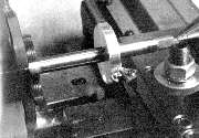 the 24dp system. This is the system based on diametric pitch. It is very simple, a 24 tooth gear would have a 1.000" pitch circle. The pitch circle is the imaginary circle that passes approximately through the center of the teeth. A 12 tooth gear would have a pitch circle of .500". For these to mesh properly they would have their centers 1.000/2 + .500/2 inches apart, or .750". The distance is the sum of the two pitch circle radii. The outside diameter is the number of teeth +2 divided by the dp. For our 30 tooth gear, this would be 32/24 or 1.333". The 15 tooth gear would be 17/24 or 0.708". The depth of the tooth is 2.157 / dp or in our case 0.090". The tooth depth is essentially the same for all gears of the same dp. For 30 divisions 40/30 = 1 and 1/3. I had the plate with 18 holes on the head, so 1/3 of 18 is 6. Great, so I will use 1 turn and 6 holes on the 18 for my spacing. Since the 15 tooth gear would require half as many steps, I just double the setting for 30 teeth and use 2 turns plus 12 teeth on the 18 tooth disk.
To make the 30 tooth gear, we drill and ream the end of a piece of 1.5" aluminum bar stock. Then a slab .250" thick is parted off. This is the rough 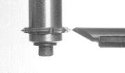 blank. It is then pressed onto a 3/8" tapered mandrel. This mandrel has a center cut at each end, and a slight taper along it's length. The + sign at one end of the mandrel signifies the larger end. Placing the mandrel in the lathe, with the large end toward the headstock, the blank is turned to the proper diameter. Also, profiling of the sides of the gear can be done at this time. I use an Adjust-Tru chuck to hold the mandrel, but turning between centers is the best way for most lathes.
The next step is to carefully set the gear cutter to the proper cutting height. I generally do this using the eyeball method and the tail stock ( or better yet, the drive center ) of the dividing head. This is very important to get right, because the gears will not run smoothly if the teeth are off-center ( been there, done that ).
blank. It is then pressed onto a 3/8" tapered mandrel. This mandrel has a center cut at each end, and a slight taper along it's length. The + sign at one end of the mandrel signifies the larger end. Placing the mandrel in the lathe, with the large end toward the headstock, the blank is turned to the proper diameter. Also, profiling of the sides of the gear can be done at this time. I use an Adjust-Tru chuck to hold the mandrel, but turning between centers is the best way for most lathes.
The next step is to carefully set the gear cutter to the proper cutting height. I generally do this using the eyeball method and the tail stock ( or better yet, the drive center ) of the dividing head. This is very important to get right, because the gears will not run smoothly if the teeth are off-center ( been there, done that ).
 Set the dividing head to zero. Turn the handle until it drops in a hole on the 18 hole circle. It is a good idea to mark this hole since it is "HOME" position. Set the sector arms for six holes as calculated above. Practice cranking the head through several cycles and make sure the degree wheel reads as you would expect. I always operate my dividing head handle clockwise. This helps to prevent confusion. Bring the head back to zero and HOME.
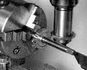
Mount the mandrel in the head and tailstock. Make sure the thrust from the cutting operation will be toward the + end of the mandrel. Bring the cutter up to the workpiece until it just touches. Zero out the cross feed. Advance the cross feed
Set the dividing head to zero. Turn the handle until it drops in a hole on the 18 hole circle. It is a good idea to mark this hole since it is "HOME" position. Set the sector arms for six holes as calculated above. Practice cranking the head through several cycles and make sure the degree wheel reads as you would expect. I always operate my dividing head handle clockwise. This helps to prevent confusion. Bring the head back to zero and HOME.
Mount the mandrel in the head and tailstock. Make sure the thrust from the cutting operation will be toward the + end of the mandrel. Bring the cutter up to the workpiece until it just touches. Zero out the cross feed. Advance the cross feed 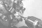 for the first cut, be sure not to run the mill too fast, those cutters are expensive. Cut all teeth at a setting, then move the cross feed. The final depth will be 0.090" as calculated above. Just be careful not to lose count on the dividing head. At the end of each pass, you should find yourself back to the HOME position. If not, well that's why they call it scrap. Lastly, the gear is removed from the mandrel and the keyway is broached.
The pinion gear blank was machined and left on the bar stock.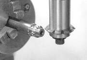 This piece can be center-drilled and put on the dividing head between centers, or held in the chuck.
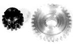 In this way, the dividing head can be used to drill and tap the setscrew holes.
Hints and Kinks
When grinding cutting tools to an accurate profile it is difficult to make the tool and prevent the layout from getting destroyed by the heat of grinding. Neither Dykem blue or magic marker stand up very well. Here is the answer. Mix a dilute solution of Copper Sulfate ( Blue Stone ) and water. A couple of small lumps dissolved into water is fine. Add a drop or two of Sulfuric Acid ( Battery Acid ). The acid is not necessary, it just makes it work better. Degrease the toolbit, then paint a drop or two of the solution on the bit. It will immediately leave a thin coating of copper plate on the bit. Wash off in water, then scribe the profile in the copper plate. The copper will not burn off during heating, and since it is very thin, it is possible to engrave extremely fine lines.
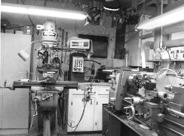
Shop of the Month
This shop is where George Carlson grinds away. A 1955 Bridgeport and a much more recent 12" lathe are the main machine tools. This shop has been added to and updated for about 18 years, so it has quite a collection of tooling both shop made and purchased. The shop was , and is, paid for by doing small specialty jobs, especially in the electronics industry.