Lawney Morales, John Korman |
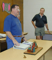
George Edwards with Model Engineering Info |
Membership Information Membership is open to all those interested in
machining metal and tinkering with machines. The purpose of the club is
to provide a forum for the exchanging of ideas and information. This includes,
to a large degree, education in the art of machine tools and practices.
There is a severe shortage of written information that a beginning hobbyist
can use. This makes an organization such as this even more important. For
membership information and forms, call Keith Mitchell at the phone numbers
shown at the left.
Notes from the President
By: Keith Mitchell
I thought our Third Annual Swap meet was a great success. Thanks to George Edwards and Rutland Tool's Dave Adamek and Bryant Sanford. To show our appreciation to Rutland we presented custom made pens with the Rutland Tool logo to Dave and Bryant. We also furnished a bar-b-que lunch to all the Rutland employees who helped with the sale. As I said before, I don't think anyone went away disappointed. When you are in Rutland let them know how much we appreciate their support.
We are actively looking for a new meeting location. The Oak Forest Library has met our needs until now. We can accommodate approximately 35 people. The last few meetings we have been close to overflow. John Korman located the Collier Library which is not far from our current meeting location. Would be ideal to find a shop where we could do demonstrations. Any suggestions?
The October meeting presentation is by Tom Moore. The topic is tailstock tooling (subject to change). The November Newsletter feature article will be "Home Brew CNC" by Jan Rowland.
Vance Burns had made progress on the new member package. This will be an info package for new club members. So far we plan to include the club member list, info on the library including an index to the contents, Club Bylaws, Club Treasury, and a "getting started" article to incorporate things such as Bill Sperry's article on selecting a lathe, George Carlson's article on Mill accessories, etc. If you would like to contribute to this effort or have suggestions, please see either Vance or myself.
Dues are due. Please see Gordon Lawson to pay for this year.
September Meeting Minutes
By: Dean Eicher
Chips Meeting - 1:00 P.M. September 18, 1999, Oak Forrest Library
Attendance - 36, Three first time attendees
In the Chips Meeting the following activities took place.
1. New Member Information Kit - Vance Burns will help organize the
new member information kit.
2. Feature Presentation - George Carlson talked about setting up the
'Ideal Shop' and Rules of Machine Purchasing based upon the types of design
and construction projects one anticipated encountering. Before purchasing
a machine, George suggested asking yourself the following three questions:
1. Does this machine allow you to do something you cannot currently do?
2. Will this machine make the hobby more enjoyable? 3. Do you have adequate
space for the machine? George then proceeded to list the following classes
of work associated with a project: Material preparation or cutting to rough
size, machine operations such as lathe and mill work, metal joining, and
finish operations. Sizes and types of machines to perform these operations
were then briefly discussed.
3. Swap Meet - Our next swap meet will be at the Rutland Tool parking
lot at 7:30 A.M. October 9, 1999.
4. George Edwards - brought supplier catalogs for the club library.
He also brought his notebook of pictures of engines and their parts and
supplies catalogs.
5. Joe Williams - brought his three handled mill vise wrench, some
thread chasers, and his bandsaw blade silver soldering jig.
6. Dick Kostelnicek - showed his tool bit height checking device which
incorporated a small bubble tube level. Dick also brought his hand feed
small floating drill chuck that can be powered by a drill press or mill.
7. George Carlson - brought a brass lathe change gear that he made
to permit cutting metric threads on his lathe. He also brought an aluminum
ring with a fine pitch metric thread that fit his camera.
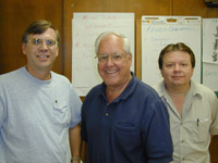
8. First Members Picture - After the meeting, three of the six members
who attended the first meeting in May of 1996 had their picture taken.
Lawney Morales, John Korman |
George Edwards with Model Engineering Info |
There are many applications of lapping in precision metalworking. We can divide these into two categories: equalizing lapping and form lapping. Equalizing lapping is used to establish or improve the fit between two components of an assembly. In this case, the two shapes mutually improve each other, and a non-embedding form of lapping is usually desired. Examples of this are lapping together of gears to improve smoothness of running or the lapping of valves into their seats to improve the seal.
In form lapping, the concern is to establish some absolute geometric shape or dimension, such as flatness, roundness, parallelism, length, or diameter. For flat surfaces, this is usually done by producing an accurate reference surface and transferring it to the work by means of embedded lapping. Cylindrical objects can be lapped by rolling them between two flat laps. Cylindrical lapping (both internal and external) may also be performed using a cylindrical lap. Complete spheres, such as ball bearings, may be produced to a high degree of accuracy by specialized lapping processes.
In addition to high geometric accuracy, useful characteristics of lapping include low removal rate, cool operation, low surface roughness, and high reflectivity.
5.1 Lapping Machines
The lapidary's lap is a soft metal disk (typically tin or copper) rotating
about a vertical axis, charged with an abrasive, and usually run wet. Machines
for lapping metal have the same basic form,
but contain a number of refinements.
Figure 9 is a simplified representation of a lapping machine. The lapping plate (usually cast iron) is grooved to insure even distribution of the abrasive, which is applied in the form of a slurry. The parts to be lapped are placed inside the truing rings which, due to the difference in drag around their circumference, rotate in the direction shown.
This rotation has two purposes: it keeps the workpieces in motion, insuring that they are lapped evenly, and it equalizes the wear on the lapping plate, helping to maintain its flatness. For small workpieces, a pressure plate fitting inside the ring is used to increase the applied force.
Figure 9.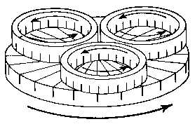
By adding a second lapping plate facing downward and replacing the truing
rings with appropriate fixtures, workpieces may be lapped parallel or cylindrical.
A high degree of parallelism may be achieved by redistributing the workpieces
several times during the course of the lapping. In this way any tendency
to form a wedge will be eliminated by redistributing the high spots uniformly
around the surface. This is how gage blocks are made.
5.2 Hand Lapping
Although conceptually simple, lapping machines are expensive and often quite large. In the home shop, lapping is usually done by hand. In this case, the lapping plate remains stationary and the work is rubbed across it by hand. The pattern of rubbing must cover the entire plate to evenly distribute the wear and maintain flatness.
A lapping plate may be produced by grinding, scraping, or the mutual refinement process described above. Plates for finishing are usually smooth, but roughing plates are often grooved in a circular, radial, or square pattern. The grooving provides a reservoir for fresh abrasive and a repository for swarf.
The lapping plate may be charged continuously, with loose abrasive, slurry, or paste applied before each use, or it may be given an initial charge with loose abrasive which is rolled or pounded in and used repeatedly before recharging.
5.3 Lap Materials
The traditional material for the flat lapping of hardened steel are cast iron and brass. In cylindrical lapping, the mutual refinement process is essential to producing accurate geometry, so laps of copper and lead are often used. The softer laps also produce a smoother finish and allow softer materials to be lapped.
Some low-precision lapping operations use free abrasives with a hard lap, such as hardened steel or glass.
5.4 Abrasives
The abrasives used in lapping include those used in grinding and other metalworking operations: aluminum oxide, silicon carbide, and diamond. These are available as loose grit, as premixed pastes, or in bonded abrasive sheets with cloth, paper, or plastic (lapping film) backings. Because of the low temperatures involved in lapping, diamond may be used successfully on steel and CBN is not necessary. However, boron carbide lapping compounds are available as an economical diamond substitute. Other (softer) abrasives are used in polishing, for example rouge (iron oxide), cerium oxide, tin oxide, and chrome oxide.
5.5 Fluids
Although lapping can be performed dry, in most cases a liquid is used along with the grit. The most commonly used fluids are water, kerosene, oil, and grease. This fluid may have one or more of several purposes:
1. A vehicle for carrying the abrasive. In hand lapping the grit can
be sprinkled onto the lapping plate. A more uniform distribution and easier
application can be achieved by mixing the grit into a slurry or paste.
In machine lapping where continuous replenishment of the grit is necessary,
supplying the abrasive in a slurry is an essential part of the process.
2. A lubricant. The lateral force in abrasion due to rubbing between
the grain and the work is only a small fraction of the total, so lubrication
can provide only a slight improvement in efficiency. More important is
rubbing between the lap itself and the work, where lubrication can prevent
sticking and galling.
3. A coolant. Heat is not a problem in hand lapping, but machine lapping,
even though much cooler than grinding, can generate significant amounts
of heat.
4. Control of grit motion. A viscous medium such as heavy grease can
retard the rolling motion of the grit, resulting in an abrasive action
which is a hybrid of rolling and cutting.
5. Removal of debris. As the work is worn away, particles of swarf
collect on the surface of the lap. If these are not flushed away, they
will build up to the point where they will clog the lap.
6. Chemical action. In some cases the lapping fluid acts chemically
on the work material to accelerate the lapping process.
5.6 Polishing
As the lapping process progresses through increasingly finer abrasives, the size of the resulting scratches becomes smaller. As these approach the wavelength of light (about 1/2 micron or 2/100,000 inch) the surface goes from a dull, diffusely reflecting to a bright, specularly reflecting one. However, if the hardness of the lap is maintained as the particle size is reduced, it becomes difficult to achieve this bright finish uniformly across the surface of the work.
In polishing for cosmetic purposes, a soft backing is used to allow the polishing abrasive to conform to the shape of the work. This same principle is used in precision polishing, but care must be taken to see that the backing is not so soft that it destroys the accuracy of the surface. One approach is to use a lap of softer material, such as tin, copper, lead, or even wood. Another is to use an intermediate flexible layer between a hard reference surface and the work.
6. Summary: Characteristics of Lapping
1. Accurate Geometry. Highly accurate plane, spherical, or cylindrical
surfaces may be generated or imparted by lapping.
2. High Dimensional Accuracy. Material is removed from the workpiece
at a slow, consistent rate. This makes it easy to control dimensions to
a high degree of accuracy by controlling the amount of time the piece is
lapped.
3. Slow. The down side of the low removal rate is that unless the work
is very close to the required dimension and shape when lapping is begin,
it will take a long time to get it there.
4. High Surface Finish. Highly reflective surfaces with roughness down
to a few microinches are easily achieved.
5. High Surface Quality. Because of the low temperatures and forces
involved, surface damage is much lower than grinding or cutting operations.
6. Simple Tools. Unlike conventional machining where high precision
requires sophisticated machinery, lapping needs only a flat plate and some
grit. However, the accuracy achieved depends strongly on the skill with
which these are employed.
7. Bibliography
As I said, much of this was learned from books. Here are a few of them.
ASTME (1949). Tool engineers handbook. McGraw-Hill, New York.
Deve, C. (1945). Optical workshop principles. Adam Hilger, London.
Farago, F. T. (1980). Abrasive Methods Engineering, Vol. 2. Industrial Press, New York.
Ingalls, A. G., ed. (1946). Amateur telescope making, advanced. Scientific American, New York.
Ingalls, A. G., ed. (1951). Amateur telescope making: book one [4th ed.]. Scientific American, New York.
Moore, W. R. (1970). Foundations of mechanical accuracy. Moore Special Tool Co., Bridgeport.
Nakazawa, H (1994). Principles of precision engineering. Oxford.
Rabinowicz, E. (1970). Polishing. Scientific American, v218, p91.
Shaw, M. C. (1996). Principles of Abrasive Processing. Claredon Press, Oxford.
Twyman, F. (1952). Prism and lens making; a textbook for optical glassworkers. Hilger & Watts, London.
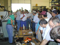 Auction in progress
 |
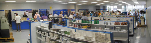 A typical Saturday at Rutland!
 |
