Volume 8, No 9 - September, 2003
|
|
Volume 8, No 9 - September, 2003 |
|
|
|
|
|
| President - |
Vice President - |
||
| Treasurer - |
Secretary - |
||
| Webmaster - |
Editors - |
||
| Founder - |
SIG Coordinators - |
Statement of Purpose
Membership is open to all those interested in machining metal and tinkering with machines. The club provides a forum for the exchanging of ideas and information. This includes, to a large degree, education in the art of machine tools and practices. Our web site endeavors to bring into the public domain written information that the hobbyist can understand and use. This makes an organization such as this even more important.Regular Meeting
 At
the Collier Library, 6200 Pinemont, Houston, Texas, August 9, 2003, 1:00 pm. Tom Moore, President, presiding. There were 44 persons present
including five visitors: S. Marion, W. Murrey, B. Chambers, R. Chandler,
and D. Johnson.
At
the Collier Library, 6200 Pinemont, Houston, Texas, August 9, 2003, 1:00 pm. Tom Moore, President, presiding. There were 44 persons present
including five visitors: S. Marion, W. Murrey, B. Chambers, R. Chandler,
and D. Johnson.
The President announced a dues increase from $12 to $15 per year. Dues for 2003-4 are due now.
At the next meeting we'll be having a discussion on lathe radius attachments.
Bring your's to the meeting. All of them if you have several styles. Photos of
their use would be helpfull.
Business Meeting
Minutes are sent via email or regular mail to club members.
Presentation
 The
program
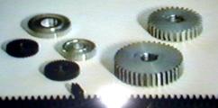
consisted of showing a video by Rudy Kouhoupt How to Cut Spur Gears. Using a small mill
and lathe, he demonstrated how to cut a replacement aluminum spur gear for his
lathe.
The
program
consisted of showing a video by Rudy Kouhoupt How to Cut Spur Gears. Using a small mill
and lathe, he demonstrated how to cut a replacement aluminum spur gear for his
lathe.
Show and Tell
|
|
|
|
|
|
|
|
|
|
No activity reported this month. |
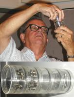
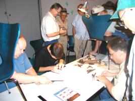 Semi-precision
layout practice. The novices were given blued (Dykem) steel plates (approx. 2x6x1/8-in.)
along with calipers, rulers, scribers, center punches, prick punches, hammers,
etc. They were requested to layout a small drawing on the plate and
center punch as needed. They could inspect their work on an optical magnifier
to see how close they hit the scribed lines. Also they tried an inexpensive
layout coating for steel made from a copper sulfate solution and a layout measuring
method using the back shoulder of a dial calipers in place of a machinist's
square.
Semi-precision
layout practice. The novices were given blued (Dykem) steel plates (approx. 2x6x1/8-in.)
along with calipers, rulers, scribers, center punches, prick punches, hammers,
etc. They were requested to layout a small drawing on the plate and
center punch as needed. They could inspect their work on an optical magnifier
to see how close they hit the scribed lines. Also they tried an inexpensive
layout coating for steel made from a copper sulfate solution and a layout measuring
method using the back shoulder of a dial calipers in place of a machinist's
square.
Next time we'll drill out the center punched holes, so bring safety glasses w/side shields
or goggles.
Featured Articles
Three model stationary Corliss steam engines have recently shown up around the club. What makes the Corliss engine stand out from other stationary steam engines is the efficient use of the energy stored in the steam.
A conventional engine injects steam at constant pressure throughout the power stroke of the piston. During the exhaust cycle, the spent steam is dumped at full pressure into the atmosphere, thereby wasting the remaining compressive and heat energy contained in the exhaust. Engine speed is controlled by throttling the input steam pressure to a lower value through a restrictor valve prior to its entering the cylinder.
In the Corliss engine, full steam pressure is applied for only a portion of the power stroke. For the remainder of this stroke the steam is allowed to expand on its own, thereby lowering its pressure and temperature before being exhausted to the atmosphere. The Corliss uses the stored thermodynamic energy during expansion that the conventional engine wastes by venting. The exact point of steam cut-off is load dependent and is sensed by a flyball governor (a mechanical feedback speed regulator).
|
|
|
 First
off, let me tell you that I'm not an expert on tool posts, However, recently
I've acquired some practical experience in fitting them to my lathe.
First
off, let me tell you that I'm not an expert on tool posts, However, recently
I've acquired some practical experience in fitting them to my lathe.
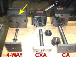
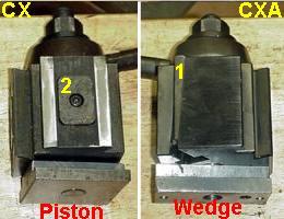
Tool posts serve two functions. They hold the cutting tool and provide a method of changing tools for various jobs. All tool posts are not the same. They employ different means for securing the tool holder, and hence, the quality of work produced is different. Basically, the more solid a machine is, the better quality work that it can produce. Since the tool post is part of the machine, rigidity is paramount. Starting with the standard 4-way indexing tool post, shown at the left, to an Aloris CX piston-style to the CA wedge-style tool post, the cutting process has gotten better and easier.
Aloris offers different sizes as well as different tool post locking mechanisms. Sizes are AX & AXA, BX & BXA, CX & CXA, CA, DA and EA. As the letter size moves along the alphabet; A, B, C etc.; the tool post get larger to accommodate a greater lathe capacity. At letter C, there are three different types. The CX and the CXA are the same size, while the CA is almost twice as large. In the past I think Aloris has made a plain C which may have been the same size as the CA. The final "A" indicates a wedge style. Those not ending in "A" are piston styles.
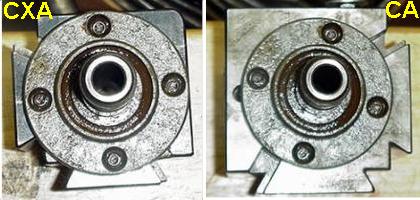
The CX and the CXA in the above right photo are different. The CX pictured is actually a Yuasa brand, but it is the functional equivalent of the Aloris CX, and indeed many of the tool post parts seem to be interchangeable. The tool holders, however, are definitely interchangeable. The CX is a piston type while the CXA is a wedge type tool post. "Wedge" is incorrect. The tool post is actually a "gib" style. Although a gib is a wedge, when used in a machine tool for tightening slides, it is referred to as a gib and not a wedge. The gib at number "1" in the photo moves up and down with movement of the locking handle in order to tighten and release the tool holder. The piston at number "2" moves in and out to tighten and release the tool holder.
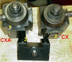 Aloris advertises the CXA style to have a greater degree of
repeatable accuracy than the CX style, although the CX is plenty
accurate for all but machining in considerably less than .001-in.
increments. The problem with the CX, for us normal machinists, is not
its accuracy. It involves the way it interacts with different
tool holders. The tool holder marked number "3" in the photo
at the left holds a boring bar and works only on a CXA style post. The parts near the "3" are
spring loaded plungers that, when pushed in, exert force on the boring
bar to hold it in place. This makes the tool holder itself a
"fast change" mechanism because the boring bar is freed when the
handle on the tool post is loosened.
Aloris advertises the CXA style to have a greater degree of
repeatable accuracy than the CX style, although the CX is plenty
accurate for all but machining in considerably less than .001-in.
increments. The problem with the CX, for us normal machinists, is not
its accuracy. It involves the way it interacts with different
tool holders. The tool holder marked number "3" in the photo
at the left holds a boring bar and works only on a CXA style post. The parts near the "3" are
spring loaded plungers that, when pushed in, exert force on the boring
bar to hold it in place. This makes the tool holder itself a
"fast change" mechanism because the boring bar is freed when the
handle on the tool post is loosened.
The gib and dove tail of the CXA pull the tool holder toward the tool post. This puts pressure on the boring tool holder and the plungers in the tool holder resulting in tightening the holder on the post and tightening the boring bar in the holder at the same time. The CX tool post pushes the tool holder out away from the tool post to tighten it. That takes pressure off of the plungers on the boring bar holder, thereby making this holder useless with a CX tool post. Boring bar holders with the more normal set screw retaining method are more common and work equally well on both piston and gib style tool posts. For many commercial machine shops and most home hobby shops the CX style is perfectly adequate. It is also cheaper. Tool holders that take advantage of the CXA's gib capabilities to tighten the tool as well as the holder are more expensive.
|
|
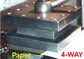
I've recently been involved with three types of tool posts, shown disassembled in the above photo at the left, that are all designed to work with my 17-in. Cincinnati lathe. The 4-Way was on the lathe at the time of purchase. It appears quite substantial when compared to the CXA and CA. However, the CXA is noticeably more stable than the 4-way, while the CA is more stable yet. My experience is that among these three tool posts they become more rigid in the following order: 4-way, CXA, CA. Although the hold down bolt, shown in the photo at the left, get progressively larger from left to right, that is not enough to account for difference in rigidity. The arrow in the picture on the left is pointing to part of the rotating portion that allows the 4-way tool post to rotate for indexing in different position. When the hold down bolt is tightened, there is a small gap between the 4-way tool post and the lathe's compound T-slot. The square part of the 4-way does not touch the compound. I was able to slide a piece of paper between the compound and the tool post as shown in the first photo in this article. Only the smaller round rotating part contacts the compound.
In the photos above, the center photo is the CXA with the round portion of the 4-way sitting on top to illustrate the relative tool post footprint that contacts the lathe's compound. The right photo is the same 4-way part sitting on the CA tool post. The CXA produces a larger contact area than the 4-way, while the CA's footprint is larger yet, thereby yielding a more rigid machining capability.Conclusions
The
Aloris web site: http://www.aloris.com/ shows only a picture of their catalog cover with no other web pages, but
there are pictures of some of the various tooling on the catalog
cover. The knurling tool at about the 8:00 o'clock position on that
catalog cover in a CA size is 2 ounces shy of 8 pounds and lists for
$285.
A Shaper
Tool Holder
by J. R. Williams - HMSC Member
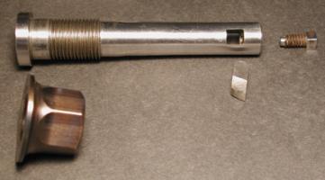 The
shaper tool is made to fit in the clapper of my Logan Shaper. The body is made
from an old B-7 stud bolt (4130) and is 4-5/16 inch long. The large end is 0.990
dia. x 0.220-in. long. The next section is 0.750 dia x 0.350-in. long before
the threaded section. The threads are 3/4-16 NF. The remainder of the shank
is 0.650-in.dia. near the threads to make starting the nut easier and tapering
in a couple steps to 0.625 inch diameter. The tool bit holding section is a
1/4 inch square hole set back 0.350 from the end. The clamp screw is a square
head, 1/4-20 NC, set screw with a dog point machined on the end. The slot
was made by machining a slot in the end with an enlarged section for the filler
section and silver soldered in place. The parts were machined to provide
a tight fit with the silver solder tape in place. Flux was applied and the silver
solder flowed to finish the job. Then the part was held on the threaded section
in a collet to finish the end OD. and drill and tap the end for the set screw.
The nut was bored and threaded in the lathe using an old flanged nut for stock
then the hex was reduced to 15/16-in. from the original 1-1/8-in.. The nut was
heated with a torch to the blue temperature and quenched in oil
The
shaper tool is made to fit in the clapper of my Logan Shaper. The body is made
from an old B-7 stud bolt (4130) and is 4-5/16 inch long. The large end is 0.990
dia. x 0.220-in. long. The next section is 0.750 dia x 0.350-in. long before
the threaded section. The threads are 3/4-16 NF. The remainder of the shank
is 0.650-in.dia. near the threads to make starting the nut easier and tapering
in a couple steps to 0.625 inch diameter. The tool bit holding section is a
1/4 inch square hole set back 0.350 from the end. The clamp screw is a square
head, 1/4-20 NC, set screw with a dog point machined on the end. The slot
was made by machining a slot in the end with an enlarged section for the filler
section and silver soldered in place. The parts were machined to provide
a tight fit with the silver solder tape in place. Flux was applied and the silver
solder flowed to finish the job. Then the part was held on the threaded section
in a collet to finish the end OD. and drill and tap the end for the set screw.
The nut was bored and threaded in the lathe using an old flanged nut for stock
then the hex was reduced to 15/16-in. from the original 1-1/8-in.. The nut was
heated with a torch to the blue temperature and quenched in oil
Inexpensive Flood
Coolant Pump
by Dick Kostelnicek - HMSC Member
 When
machining with flood cooling, a liquid is flushed over both the cutting
tool bit and the work. This prevents annealing of the cutter's edge
and heat distortion in the work. Water is by far the best cooling fluid.
Not only is it cheap, but it has one of the highest heat capacities of all common
liquids. However, it will rust your machine tool unless you add a
rust inhibitor such as soluble cutting oil. I add 2-oz per gallon, which
produces a milky white liquid. Now, the oil is not meant to lubricate the cut,
just inhibit rust. After several weeks of use, the total volume of coolant
will diminish due to the heat generated during machining and normal surface evaporation. Add distilled water to bring up the volume in the reservoir and add just
a bit of replacement soluble oil. Periodically, screen off the reservoir's
surface in order to capture the congealed mass that floats on top.
The floaters are the result of biological growth and "tramp"
or non soluble machine oil. Every few months, filter all of the liquid,
remove the metal cuttings, and clean the reservoir container's walls.
When
machining with flood cooling, a liquid is flushed over both the cutting
tool bit and the work. This prevents annealing of the cutter's edge
and heat distortion in the work. Water is by far the best cooling fluid.
Not only is it cheap, but it has one of the highest heat capacities of all common
liquids. However, it will rust your machine tool unless you add a
rust inhibitor such as soluble cutting oil. I add 2-oz per gallon, which
produces a milky white liquid. Now, the oil is not meant to lubricate the cut,
just inhibit rust. After several weeks of use, the total volume of coolant
will diminish due to the heat generated during machining and normal surface evaporation. Add distilled water to bring up the volume in the reservoir and add just
a bit of replacement soluble oil. Periodically, screen off the reservoir's
surface in order to capture the congealed mass that floats on top.
The floaters are the result of biological growth and "tramp"
or non soluble machine oil. Every few months, filter all of the liquid,
remove the metal cuttings, and clean the reservoir container's walls.
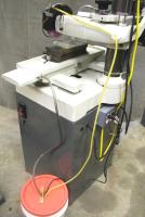
I paid around $200 for my first coolant pump, tubing, and spray nozzles that I installed on a column-n-knee milling machine. I soon found that I could either make or buy the component parts at my local home improvement store, for a substantially lower cost. Since then, I have installed my home made flood cooling equipment on a lathe, a horizontal band saw, and on the surface grinder shown in the accompanying photos.
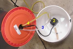
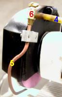 The
basic components are: (1) Two to five gallon plastic
pail with lid for the reservoir. (2) Small capacity $25 submersible
water fountain pump. (3) 3/8-in. ID clear vinyl tubing for the return
hose. (4) 3/8-in. OD latex hose for fluid delivery. (5) Length
of 1/4-in. copper tubing to serve as the discharge nozzle. (6) Any
kind of small valve to moderate the fluid flow.
The
basic components are: (1) Two to five gallon plastic
pail with lid for the reservoir. (2) Small capacity $25 submersible
water fountain pump. (3) 3/8-in. ID clear vinyl tubing for the return
hose. (4) 3/8-in. OD latex hose for fluid delivery. (5) Length
of 1/4-in. copper tubing to serve as the discharge nozzle. (6) Any
kind of small valve to moderate the fluid flow.
The copper nozzle is fashioned by flattening the tip of the copper tubing in order to force the fluid to fan out. Put a 0.020-in. thickness shim in the tubing end just as it is finally flattened. Then pull out the shim leaving an elongated thin slit orifice. The valve, seen in the photo at the right, goes between the copper tube and latex hose. I used a 1/4-in. auto radiator drain valve. The valve is not used to turn on and of the fluid, but merely regulate the volume of discharge. An electrical switch turns on and off the pump, so that the regulator valve setting can remain fixed between uses. For low pressure supply hose, I use surgical latex tubing because it will expand to fit most any size hose barb found on small submersible pumps and discharge valves. Additionally it is super flexible and does not harden with age.
The return tube is clear vinyl, That way I can see if there is any blockage in the gravity fed return flow. This tube should not have any U-traps in its decent to the reservoir bucket. That would cause pooling of the fluid at the low point in the hose, thereby resulting in vapor lock that will prevent fluid from draining from the machine. Furthermore, prevent the discharge tube from being submersed in the reservoir liquid. This also can contribute to vapor lock. I use pieces of a flat wood paint stirring stick attached to the vinyl tube with tie wraps both above and below the hole in the reservoir lid. This prevents the discharge tube from pulling out of the reservoir (possibly spilling coolant on the shop floor) and keeps its end out of the bulk liquid. The result is reliable return flow of spent coolant.
My experience indicates that the pump should always turn on
and off along with the machine's work motor. Additionally, provide a switch to disable
the pump when its use in not desired. On 110V work motors, just parallel the pump
with the motor. On 220V single phase motors, connect the 110 V
pump between one side of the supply line to the center tap of the two series
connected motor run windings. On 220V 3-phase motors you'll just have to use
a 220V relay connected to one of the motor windings to control the operation
of the submersible
pump.
|
Visit Our Web Site |
 |
Right click below then select [Save
Target As...]
From Netscape select [Save Link As..]
Microsoft
Word version of this newsletter 378 KB


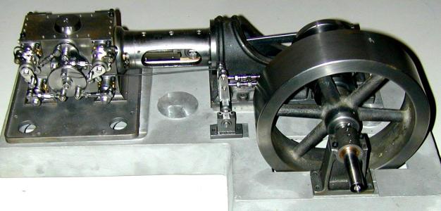 Dick
Kostelnicek is building his engine from a set of castings available from
Dick
Kostelnicek is building his engine from a set of castings available from
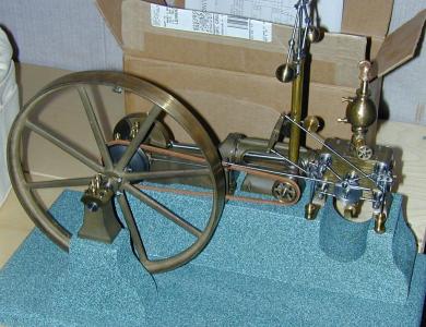
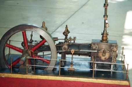 Pat Stanush of San Antonio TX sent in pictures of his antique
(probably 75 years old) Corliss engine that he bought several years ago from
a friend who obtained it in Maine. Great attention was given in its construction (see
the railing details) and it is on a cast iron base. Besides engines, Pat collects 19th
century machinist's hand tools.
Pat Stanush of San Antonio TX sent in pictures of his antique
(probably 75 years old) Corliss engine that he bought several years ago from
a friend who obtained it in Maine. Great attention was given in its construction (see
the railing details) and it is on a cast iron base. Besides engines, Pat collects 19th
century machinist's hand tools.