 Features / Advantages:
Implemented in 1999 and 2000
Documentation completed March 1, 2001
Features / Advantages:Changing speed without changing gears, just setting of two selector switches
This is no speed regulation, but angular position ( = phase) regulation, i.e. lead screw moves like coupled with gears.
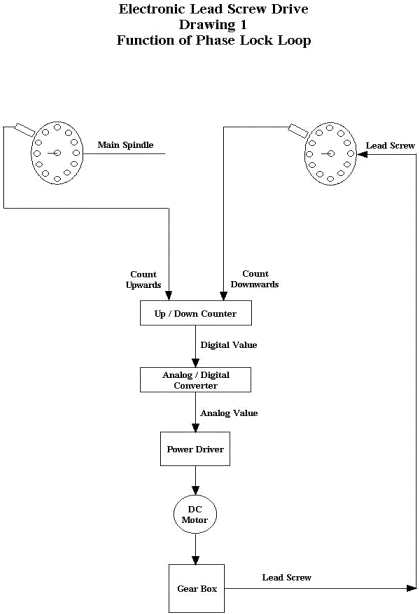
See drawing no. 1. The lead screw is driven by a D.C. gear motor , so its speed can be controlled by the operating voltage applied to the rotor. A timing disk on the main spindle generates pulses that count an electronic counter (phase counter) upwards. A timing disk on the gear motor generates pulses that count the same phase counter downwards. An electronic digital-to-analog converter (ADC) creates a voltage level depending on the count, i.e. full voltage level when the phase counter is at its maximum, or half of that value when the phase counter is at half of its maximum etc. A transistorized power driver converts the (variable) voltage level from the ADC to a (variable) voltage with enough power to drive the gear motor.
Assume both, the main spindle and the lead screw drive, are running. Regarding their speed relation, there are 3 possibilities:
The lead screw will always run at a speed that keeps the phase counter in balance. The regulation process as per above takes place within milliseconds and reacts at count differences of single pulses, thus ensuring precise synchronism. Since this is not a speed regulation, but a regulation of angular position, there is no accumulation of speed deviations. The gear motor will always settle to a speed that keeps the phase counter in balance. This keeps both drives in synchronism as if they were coupled by gears.
Above will ensure a 1 : 1 coupling of main spindle and gear motor. We want, however, selectable speed rations. This is done by two additional counters, one each between main screw pulses and phase counter (main spindle / divider counter) and between gear motor pulses and phase counter (lead screw / multiplier counter). See drawing no. 2. Both counters can be preset to various values and work as frequency dividers, i.e. they pass on each nth pulse (n = preset value) to the phase counter.
Lets look at the divider counter first: If it is set to a value of, say, 3, it will only pass on every third pulse from the main spindle to the phase counter. To keep the phase counter in balance, the gear motor will now have to run only at a third of the speed. In other words, through setting the divider counter, the gear motor can move at any full-digit fraction of the main spindle speed, i.e. a half, third, quarter, hundreth etc.
Just dividing, however, does not give us all the gearing ratios required. Therefore we also need a multiplier counter: It works the same way and is arranged the same way between lead screw pulses and phase counter. When set at the value of n, it will pass on every nth gear motor pulse to the phase counter. To keep the phase counter in balance, the gear motor will now have to run at n times the speed, thus performing a speed multiplication.
Through clever setting of multiplier and divider presets, virtually any speed ratio can be generated.
The system also provides for directional sensitivity, so if the main spindle is being reversed, the lead screw will follow in the reverse direction. This will ensure the system will never get out of synch as long as power is on and the saddle is not decoupled from the lead screw. As with mechanical lead screw drives, due to mechanical backlash, you can only cut in one direction without losing precision necessary for thread cutting. For normal machining, where absolute synchronism is not necessary, reversing during operation is of course possible. Also another way of reversing is possible, i.e. reversing the lead screw while maintaining main spindle direction. This is done by flipping toggle switch S1 at the front panel.
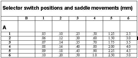
In my (metric) implementation, these saddle movements (in millimeters)
per main spindle revolution are possible through setting switches A (multiplier)
and B (divider):
 In
my implementation, with 1.5 mm saddle movement per lead screw revolution
and 40 / 120 holes in the main spindle / lead screw disk, the main spindle
preset (divider) values are 1, 2, 5, 10, 25, 50, the lead screw (multiplier)
values are 5, 6, 7, 8, 9, 10. The multiplier and divider presets are defined
by diodes on the electronics board and are selected by selector switches
A and B above.
In
my implementation, with 1.5 mm saddle movement per lead screw revolution
and 40 / 120 holes in the main spindle / lead screw disk, the main spindle
preset (divider) values are 1, 2, 5, 10, 25, 50, the lead screw (multiplier)
values are 5, 6, 7, 8, 9, 10. The multiplier and divider presets are defined
by diodes on the electronics board and are selected by selector switches
A and B above.
This is the formula for saddle travel per revolution of the main spindle:
SM = Saddle travel per revolution of main spindle
ST = Saddle travel per revolution of lead screw
PRM = Number of pulses per revolution of main spindle
PRL = Number of pulses per revolution of lead screw
MLT = Preset multiplier value
DIV = Preset divider value
GR = Gear ratio in case the lead screw disk does not sit directly on
the lead screw, but, for example, on the motor shaft. (If it does, this
value is 1).
Precision and limits of the regulation are determined by:
- ST as per formula above
- Number of pulses per revolution of both the main spindle and the
lead screw
- Size of timing holes (approx. 1 mm diameter, depending on photo sensor.)
- Upper frequency limit of the photo sensors (approx. 5 kHz)
- Upper frequency limit of electronics (approx. 20kHz)
- Gain adjustment of the power driver, i. e. higher gain brings the
gear motor to full speed at smaller angular deviation (i.e. phase counter
content). Upper limit is determined by gear motor beginning to oscillate
or gear motor not able to follow upon start of lathe at high speed
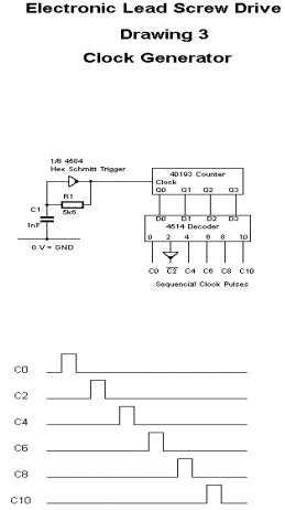 Detailed description of the circuitry: Clock Generator
(drawing 3):
Detailed description of the circuitry: Clock Generator
(drawing 3):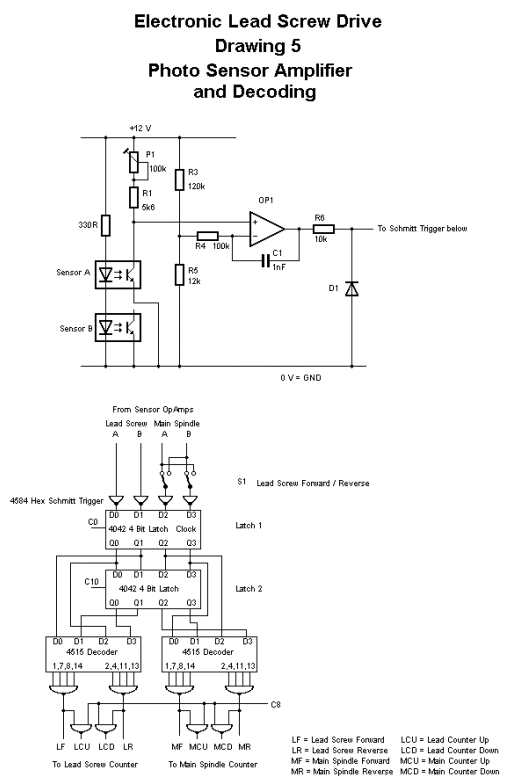 Sensor
Signal Decoding (Drawings 4 and 5):
Sensor
Signal Decoding (Drawings 4 and 5):
Drawing 4:Timing disk sensor signals. Drawing 5: The upper part shows
the sensor amplifier. Resistors R3 and R5 provide for a bias of approx.
1.2V at the OpAmp inverting input, holding the output near -12V. Diode
D1 clamps the output to a voltage higher than -.5V to protect the following
CMOS Schmitt trigger. Upon receiving light, the photo transistor
will become conductive, reducing the non-inverting OpAmp input voltage
to below 1.2V, causing the output to turn positive and trigger the following
Schmitt trigger (1/6 of 4584). C1 / R4 reduce noise sensitivity. Each of
the 2 sensors per disk need one such amplifier. Rotation of the disk and
its direction is recognized by signal status transitions, i. e. comparison
of the current status of the signals, as represented in latch 1, clocked
with clock 0, to the previous status as represented by latch 2, clocked
with clock 10. Both stati are decoded by two 4 to - 16 decoders and two
4 - input gates. Signals LF (Lead Forward) and LR (Lead Reverse) resp.
MF (Main Forward) and MR (Main Reverse) tell which disk has moved into
which direction. These signals control counting direction of lead screw
(multiplier) counter resp. main spindle (divider) counter, LCU and LCD
(Lead Count Up and Lead Count Down) resp. MCU and MCD provide the actual
counting pulses at C8 time.
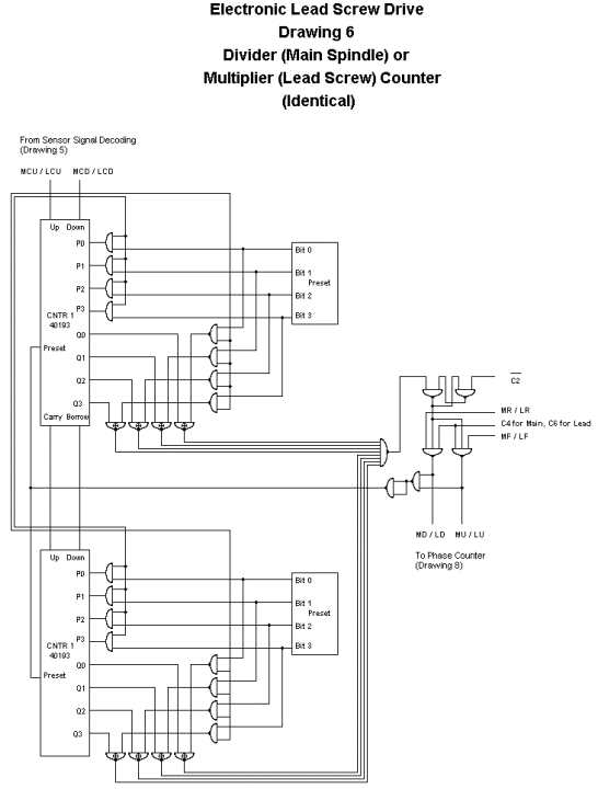 Lead Screw ( = Multiplier) and Main Spindle ( = Divider) Counter (Drawing
6):
Lead Screw ( = Multiplier) and Main Spindle ( = Divider) Counter (Drawing
6):
Both counters are identical. Since the system is bidirectional, these
counters have to be able to reverse their counting direction at any time
while counting, without losing a pulse. When counting up, they are initially
set to zero and are compared to the preset value. When the preset value
is reached, they are set to zero again. When counting down, they are set
to the preset value and compared to zero. Upon reaching zero, they are
set to the preset value again.
Each time the multiplier or divider counter is set to zero or to the
preset value, it passes on a counting pulse to the phase counter. To avoid
the phase counter to receive an up count and a down count simultaneously,
which would result in an undetermined condition with possible loss of a
pulse, pulses from the divider counter (main spindle) to the phase counter
are clocked with C4 and from the multiplier counter (lead screw) with C6.
Depending on the required preset values, as resulting from system layout,
the multiplier and the divider counter and their associated diode matrix
may have 4 digits (up to a value of 15) or 8 digits (up to a value of 255).
 Preset
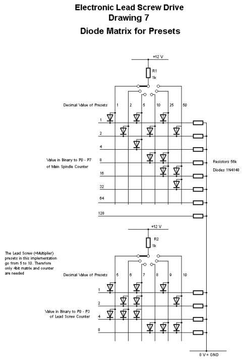
Diode Matrix (Drawing 7):
Preset
Diode Matrix (Drawing 7):
It provides binary values of the required multiplier and divider preset
values to the lead screw and the main spindle counter. In each switch position
(vertical line), where a diode connects to a horizontal line (binary value),
this value is being preset by receiving a positive voltage. All others
are grounded via the 56k Resistors. The sum of all binary values for a
preset is the decimal value. For example, in the upper preset counter,
the value of 50 is made up of 32+16+2 = 50.
Phase Counter, Digital-to-Analog Converter, Power Driver, Optional Function Display (Drawing 8):
Since the system is bidirectional, these are the counting conditions:
Forward direction of main spindle: Phase counter counts up with divider
(main spindle) pulses and counts down with multiplier (lead screw) pulses.
Reverse direction: Phase counter counts up with multiplier (lead
screw) pulses and down with divider (main spindle) pulses. The phase counter
is a 4 digit counter. The equilibrium of the system is defined at a count
of 8. Counts larger than 8 move the lead screw forward, counts smaller
than 8 reverse it. The phase counter drives 4 resistors R1 to R4, approximately
representing the 4 binary values. This way, the 2 complimentary OpAmps
receive a voltage proportional with the binary value of the counter. An
offset potentiometer at each OpAmp is set to reach zero volts at each motor
terminal when the phase counter is at 8. The gain is to be set such that
the lead screw reacts at the smallest possible main spindle rotation without
overreacting, i.e. oscillating or stumbling when the lathe is started.
This latter condition can be seen from the optional function display coming
to the highest or lowest LED. The optional function display just decodes
the phase counter content and drives a set of 16 LEDs at the front panel.
Without the unit in motion, the center LED will be on. When the lathe is
running, another LED further up will light. On reverse operation, it will
move downward. Depending on load and speed, the work of the system can
be observed.
Fritz primary interest is in integrating electronics with mechanical devices. Prior to the Electronic Leadscrew Project Fritz built a mechanical leadscrew drive. This requied machining 50 gears. During the course of that project Fritz corresponded with George Carlson. They discussed the possibility of developing an electronic solution. Initially Fritz was not convinced, however, he continued to develop the Electronic Leadscrew project in his mind and ultimately committed it to paper and hardware.
Fritz future projects include a low temperature differential Sterling engine, A windingless electric motor, and a solid state high voltage amplifier to drive electrostatic speakers.
Please e-mail Fritz to thank him for an excellent article. Part 2 of
this article will be some construction details and photos.
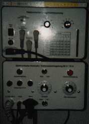
Physical layout of the system:
To build the unit, this is what you need:
Basic electronics knowledge
Soldering iron,
Multimeter
Oscilloscope
I shall be happy to provide any help and guidance beyond this documentation by email. Unfortunately I cannot assist in person, since I am located almost half way around the globe in Germany.
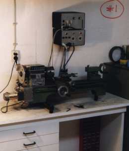
The following photographs show the physical layout in connection with
my small tabletop lathe.
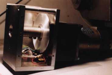
Timing Disks:
The timing disk on the main spindle has 40 holes; the timing disk on
the gear motor output has 120 holes. Considering the sensor signal decoding
as described in drawing 3, one hole gives 4 pulses, so in my implementation
there are 160 pulses per main spindle revolution and 480 on the lead screw.
The lead screw pitch is finer because of the generally lower speed of the
lead screw. The finer the pitch on both disks, the more accurate the regulation
and the smother the operation at low speed. The upper limit of pitch and
speed is given by the frequency limit of the photo sensors or by the operating
speed of the logic circuitry. The lead screw disk on my system is directly
on the lead screw, i.e. on the gear motor output, but one can also place
it on the motor itself and use a timing belt transmission with a gearing
ration other than 1:1 between motor and lead screw. This will virtually
multiply the lead screw hole pitch by the transmission ratio between motor
and lead screw.
Timing Disk Sensors:
Please refer to photograph no. 6. I use fork type photo sensors providing
light emitter (LED) at one side of the disk and light sensor (photo transistor)
at the other. Basically, also reflector type sensors could be used. They
might simplify mechanical construction in some cases. Since the system
is bi-directional, sensors also need to recognize direction of rotation.
This is achieved by using 2 sensors on each disk, phased at an angular
distance of one-quarter hole pitch plus any full number multiple of hole
pitch. (Refer to drawing no. 4). They need to be adjustable both in radial
direction (for optimum hole sensing) and in angular direction (for adjustment
of the quarter pitch phasing).
Logic Circuits:
Series 4000 CMOS logic components, that are available all over the world, are used. Types and their connection are shown in drawings 3, 5, 6, 7 and 8. All logic functions are controlled by a set of clock pulses, ensuring proper sequencing of functional steps, making the system insensitive to tolerances in component switching times, propagation delays, capacitive coupling in the wiring, etc.
Since the unit is not designed for series production, there is no circuit
board layout available. It uses a 230 by 160 mm circuit board with 1/10
inch pitch holes and soldering pads. All but power and ground connections
are run with .3 mm lacquer insulated copper wire as used in all kinds of
coils and transformers. Normal plastic insulated wires would become too
bulky. For ground and power connections I use 1 mm thick blank wires directly
soldered to the pads. Photographs 7, 8, 9 and 10 show the physical layout.
Gear Motor:
Since lathes are very different in size and construction, the detailed
construction with my small table lathe may not be representative. This
will have to be specifically designed for each type of lathe. My gear motor
with timing disk is shown in photographs 3, 4, 5 and 6.
Here are the rules for gear motor selection:
a.) Torque needs to be sufficient with a good safety margin to turn
the lead screw under maximum load.
b.) Maximum speed must match application.
c.) Motor should run smoothly at lowest possible speed.
I picked a gear motor with max. 32 V operating voltage. This allows
for simpler design of the driver electronics, because the op amps used
can operate on the same supply voltage (i.e. on plus and minus 16 V).
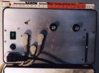
Power Driver:
The power driver is just a Darlington (two-stage) emitter follower with
adjustments for offset and gain of the OpAmps. Since the system is bi-directional,
the power stage is a bridge type circuit, allowing to apply both polarities
to the gear motor. The type of OpAmp is not critical at all, any high impedance
input OpAmp with the proper voltage handling capability will do. The power
transistors in my system handle a maximum of 2 Amps. For larger lathes
/ motors, bigger transistors and heat sinks may be necessary. Photograph
no. 11 gives an idea of the physical layout.
Power Supply:
The voltage for the gear motor and power drive circuitry (in my case
+16 V and
-16 V) does not need to be regulated. Other, regulated voltages are
+12 V for the logic circuits and the photo sensor OpAmps and
-12 V for the photo sensor OpAmps. Due to low load, the voltage regulators
(7812 and 2912) need no heat sink. Please refer to photograph no. 11.
Optional Function Display:
The work of the regulation can optionally be visualized by decoding the content of the phase counter and displaying it through a series of LEDs at the front panel.
PS:
As mentioned further above, accuracy of the regulation / minimization
of angular deviation is better with finer pitch of the timing disks. Therefore
I am in process of increasing the main spindle pitch by a factor of 3 from
40 to 120 holes and changing the lead screw drive to a motor with a 3:1
timing belt transmission, putting the 120-pitch timing disk onto the motor
shaft, giving a virtual tripling of the pitch.
Since the 2 overlapping sensors give 4 pulses per timing disk hole,
the regulation increment of the main spindle will then be 120 * 4 = 480
pulses per revolution and at the lead screw 120 * 4 * 3 = 1440 per revolution.
This way, regulation increments on both, main spindle and lead screw,
are reduced to one third, increasing precision and smoothness at low speed
by a factor of 3.