Volume 8, No 12 - December 2003
|
|
Volume 8, No 12 - December 2003 |
|
|
|
|
|
| President - |
Vice President - |
||
| Treasurer - |
Secretary - |
||
| Webmaster - |
Editors - |
||
| Founder - |
SIG Coordinators - |
Statement of Purpose
Membership is open to all those interested in machining metal and tinkering with machines. The club provides a forum for the exchanging of ideas and information. This includes, to a large degree, education in the art of machine tools and practices. Our web site endeavors to bring into the public domain written information that the hobbyist can understand and use. This makes an organization such as this even more important.Regular Meeting
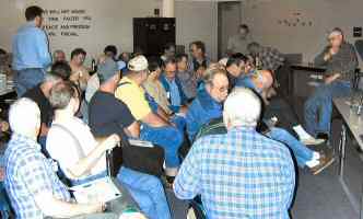 Collier
Library, Houston Texas, 1:00 p.m., November 8, 2003. 29 members were present
including 1 guest, Rick Tanueco.
Collier
Library, Houston Texas, 1:00 p.m., November 8, 2003. 29 members were present
including 1 guest, Rick Tanueco.
Art Volz won the door prize, a shop apron donated by http://www.littlemachineshop.com.. Leo Reed requested the Little Machine Shop catalogues that were distributed and they sent along the apron.
Don't forget your 2004 dues of $15. Make arrangements to pay John
Hoff - Treasurer.
Business Meeting
Minutes are sent via email or regular mail to club members.
Presentation
|
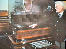
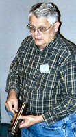
Joe Scott showed a video titled Music Box Automation by Kenith Harding. It unveiled the mechanical inner workings of numerous antique wind up and peddle operated music machines |
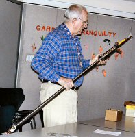
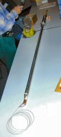
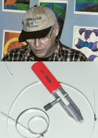
Joe Williams discussed his deep reach automatic wire feed TIG welding torch. The unit reaches deep inside and welds the inner workings oil field valve bodies. Joe has made several versions for various valve manufacturers and supports their continued operation. |
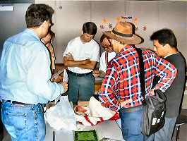
Show and Tell
|
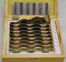
For the round-up of most useless tool that I just had to have, Dick Kostelnicek brought his set of wavy ultra thin parallels. |
Tom Moore showed his most useless keyway marking clamps that allow a straight edge to mark a shaft for key cutting, presumably the good fashoned old way with a chisel and hammer. |
Ray Ethridge brought a tightener for stainless steel bands that he picked up at a NAPA auto parts store. |
|
Rich Pichler showed off his hand powered stone sharpener. "They just don't make them like that any more." Thank goodness.! |
Joe Scott showed a collet stop that he made. He also brought in a set of double angle collets that yield no draw-in when tightened in a lathe's spindle. |
Art Volz brought a home made lathe mill vise? |
This and That
Doug Chartier's response to misused misspelled word....
A vise as a vice is a vice, of course, but a vise as a vise is a vice less vise
... or
A vise as a vice is a vice, of course, but a vise as a vise is a
vise less vice ... or
A vise as a vice is a vise, of course, but a vise
as a vise is a vice less vise ... or
A vise as a vice is a vise, of
course, but a vise as a vise is a vise less vice.
Special Interest Groups Activity
Novice
Sig
 The lathe demo will
be postponed to the January meeting.
The lathe demo will
be postponed to the January meeting.
|
No activity this month. |
Computer Numerical Control Sig No activity this month. |
Featured Articles
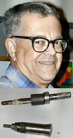
Determining the Drive Size
of a TORX� Screw
by Dick Kostelnicek -
HMSC
Member
 Recently,
I obtained some metal cutting tools that use carbide inserts. The inserts
are fastened down with Textron Corp's internal TORX� head screws. At first they
look like conventional recessed hex heads, but are really a 6-point spline.
The figure at the left shows a side view of a TORX driver and the end-on view of
the mating screw head recess. TORX drivers are designated by T-number, T1 through
T100. In order to determine the T-designation of a driver, measure
its widest part, "A" , then refer to
the table shown below. It is not, however, a simple a matter to directly
measure the recess, "B", of a Torx screw
head in order to determine the required driver size.
Recently,
I obtained some metal cutting tools that use carbide inserts. The inserts
are fastened down with Textron Corp's internal TORX� head screws. At first they
look like conventional recessed hex heads, but are really a 6-point spline.
The figure at the left shows a side view of a TORX driver and the end-on view of
the mating screw head recess. TORX drivers are designated by T-number, T1 through
T100. In order to determine the T-designation of a driver, measure
its widest part, "A" , then refer to
the table shown below. It is not, however, a simple a matter to directly
measure the recess, "B", of a Torx screw
head in order to determine the required driver size.
In the accompanying table column headed "Drill as GO-gauge", I've enumerated the drill shank sizes that will fit into the TORX recess "B" as a GO-gauge. The closest fit is shown first, followed by successively looser fits. I've tried to include a drill from each of the four categories: metric, letter, number and fractional. However, for the sizes smaller than T-15 or larger than T-45, this was not possible. All drill shanks shown are guaranteed to be NO-GO, interference fit, in the next smaller size Torx screw head.
Textron Corp. has a very good set of specifications for the TORX fastener system on the Internet at http://www.textronfasteningsystems.com/licensing/tncinch.html. The "A" and :"B" dimensions were extracted from those specs. An excellent overview of the TORX fastener system can be found at http://www.textronfasteningsystems.com/camcar/PDFS/torx.pdf.
|
|
Band Saw Blade Brazing
J R
Williams - HMSC Member
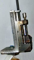
 The following describes my
procedure and a fixture used for silver soldering band saw blades ranging in size
from 1/16 thru 3/4-in. wide. The
fixture I use was originally built for brazing 1/2-in. blades for a small import
cut off saw and is currently used for blades for my Delta upright unit
and my Jet horizontal cut-off saw having a 3/4-in. blade. Even
though the blade stock being used in the large
saws is 3/4-in. Starrett high speed steel, the silver solder process provides reasonable service when a good
anneal is completed. The annealing
process is critical for the high speed steel blades. A future process to be
tried is TIG welding of the blades.
The following describes my
procedure and a fixture used for silver soldering band saw blades ranging in size
from 1/16 thru 3/4-in. wide. The
fixture I use was originally built for brazing 1/2-in. blades for a small import
cut off saw and is currently used for blades for my Delta upright unit
and my Jet horizontal cut-off saw having a 3/4-in. blade. Even
though the blade stock being used in the large
saws is 3/4-in. Starrett high speed steel, the silver solder process provides reasonable service when a good
anneal is completed. The annealing
process is critical for the high speed steel blades. A future process to be
tried is TIG welding of the blades.
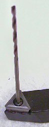
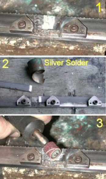
Fixture: The fixture is a section of steel bar stock ( 1/4 x 1 x 12-in.) with a reduced section about 0.035-in.deep and 7/16-in. wide. The unit was made for the 1/2-in. wide blade stock. The center section is cut away to provide space under the blade to prevent soldering the blade to the fixture. Two small clamps are installed on each side to hold the blade stock in place. They are held in place with two small guide pins (old U-joint rollers) and a #8 socket head cap screw.
Blade Preparation: The blade stock is first cut to length for the saw, adding about a half inch for the lap joint, and the ends are free hand ground to a long tapered lap joint with the bench grinder. The blade ends may require a little adjustment with a hammer to insure they match in the fixture. The stock is clamped in the fixture on the first side and flux is applied to the joint area. The second side is then clamped in place. More flux is applied along with the silver solder. The solder used can be either the ribbon form or wire. I normally use the ribbon and cut a small piece slightly larger than the lap area and slide it into the joint area or cut a small section of wire and lay it on the joint area at the lap end.
Heat Application: The torch used can be either a propane or an oxy-acetylene. I find the oxy-acetylene unit easier to control. Heat the joined area slowly to a temperature sufficient to melt the solder and after the solder flows, back off on the heat and allow the joint to cool. A short annealing pass will not hurt the joint in the normal carbon steel blade stock but is mandatory for the high speed steel blade material. The high speed steel blade joint is re-heated to slightly below the melting point of the solder and the torch's flame backed away allowing the joint to slowly cool. The process is repeated two or three more times taking the temperature to a lower point each time and allowing the blade to cool slowly.
Final Operation: The final operation is to
remove the flux with a scraper or file and grind off the excess silver solder and blade material to reduce the joint
thickness to the required blade thickness or less to provide clearance in the saw's blade guides.
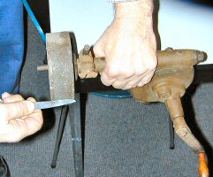
Truing
a Tired Old 3-Jaw Chuck
by Joseph Scott - HMSC Member
|
|
|
|
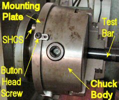
My old, import, 3-jaw scroll chuck was tired and showed considerable
run out. So, I converted it to a set-true type mounting.
I separated the mounting plate from the chuck body and milled matching
perpendicular slots across the mating surfaces. In the chuck body, the
slot was made 0.025-in deeper and wider than in the mounting plate in order
to allow slight relative movement in all directions. Keys were fitted and
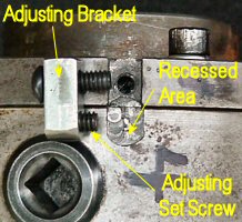
bolted into the narrower mounting plate slots. Four adjusting brackets
were bolted to the mounting plate's outer edge with button head screws.
Set screws in the brackets bear against a recessed area in the chuck
body. Flat slots were machined in the mounting plate's outer edge to accommodate
the adjusting brackets. Notice that in the leftmost photo the OD of the mounting
plate is larger than that of the chuck body, thereby accommodating relative
displacement of these two parts. The original SHCS (socket head cap
screws), holding the mounting plate to the chuck body, were loosened
slightly and the set screws adjusted for minimum run out of a test bar. The
mounting SHCS were then tightened.
Larger keys and set screws would work better, but I used what I had. This conversion could have been be done without the slots by mounting keys on the OD of the chuck and mounting plate, but I wanted the chuck OD to be fairly smooth.
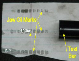
After dialing in (removing the bar's run out) the chuck with
a test bar, I tested the jaws for contact along the bar. The jaws showed less
contact towards the chuck's front, where wear was most prevalent. I preformed the test
by tightly wrapping a piece of notebook paper around a precision ground test bar and
putting oil on all jaw teeth. After tightening the jaws, oil marks were left
on the paper showing less contact in front indicating a need to grind the jaws
in order to true-them-up.
|
Visit Our Home Page at |
 |
Right click below then select [Save
Target As...]
From Netscape select [Save Link As..]
Microsoft
Word version of this newsletter 417 KB