Volume 7, No 1 - January, 2002
|
|
Volume 7, No 1 - January, 2002 |
|
|
|
|
|
|
President - |
Vice President - |
||
|
Treasurer - |
Secretary - |
Ed Gladkowski |
|
|
Web Master - |
Editors - |
|
Lary Hill |
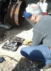
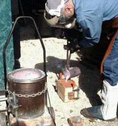
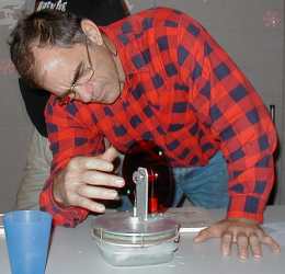
On December 1, 2001 there was a foundry workshop and demonstration at the Houston Area Live Steamers site in Zube park. Dennis Cranston, Larry Hill, and Ed Gladkowski lit off their portable furnaces and melted and poured ZA-12 alloy, aluminum, and bronze respectively. Aaron Gist brought his well thought out and well made large furnace but did not have time to light it. |
Ed Gladkowski |
Business Meeting:
December 8, 2001, 1:00 p.m., at Collier Library, 6200 Pinemont, Houston, Texas, President Dennis Cranston presiding. There were twenty-nine attendees, including visitor Kenny Tate.
It was suggested by President Cranston that a list of the club’s library holdings be published on the website, and shown once or twice a year in the newsletter. If any paid up club member notifies David Whittaker of something he wants to borrow from the library, Dave will bring it to the next regular meeting if the item isn’t already loaned out.
|
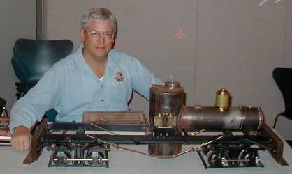
Doug Blodgett's live steam engine project
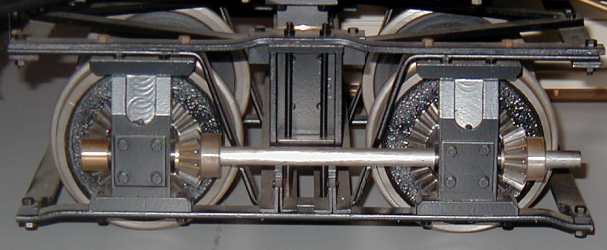
Traction gear built onto truck
|
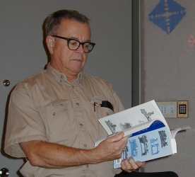
Doug Blodgett from Houston Area Live Steamers, as well as Home Metal Shop Club, showed the Mich-Cal. live steam locomotive he is building to Bill Harris’ design. He gave an enjoyable account of his trials, tribulations, and successes with the project.
|
|
|
|
||
|
|
|
||
|
|
|
||
by Tom Moore - HMSC member
Improper machine alignment will cause a lathe to turn tapered and drill/ream oversize holes. If the centers are not axially aligned, drilled/reamed holes may be tapered and attempts at small hole drilling result in wholesale drill breakage. Alignment should be checked any time the results are suspicious and always after the machine is moved. If the lathe is mounted on a wooden bench, alignment should be checked every 6 months.
The usual first step is to bring the lathe bed to a perfect level. This is easy to do, requiring only an engineers level that you can borrow or buy (a carpenters level is not adequate here). Once the bed is level, the ways should be in perfect alignment. The alignment of the centers can then be easily checked without the use of exotic devices beyond those you can easily make yourself. The most common way that the centers get out of alignment is via the ‘offset’ adjustment in the tailstock assembly. Other problems could be a loose headstock casting bolted to the bed or your using something other than the original tailstock. Occasionally the tailstock spindle will be bent or a cheap lathe being so poorly manufactured that it not practical to repair.
1. The first step is to level the lathe along both of the ways. This requires a machinist Level that can indicate an error of 0.001” in one foot. Once level is achieved, turn the Level end for end..you should observe the same result. If not, most high class Levels are adjustable. Re-adjust until the observed error is the same both ways. Some lathes have belt-in leveling screws. Adjust them until all four legs are touching the ground and the ways are level. Machines without leveling screws require shims under the table legs. Wooden wedges are available at lumber yards for installing door frames..or use wooden shingles. Once the ways are level, turn the Level across the ways at the headstock end and adjust the front and/or back legs to indicate level. Move the Level to the tailstock end and repeat. Start over and continue until the bed is level every way by less than 0.001” / foot.
2. Center alignment requires a jig that is cheaply and easily made from a piece of ‘all-thread’ about 1/2 the length of the lathe bed. Use a piece small enough to slide through the headstock spindle. You will need 4 nuts and two ‘fender washers’ (~2” OD, small hole..from an auto supply store) to fit. Next use your 3-jaw chuck to center the all-thread rod at both ends. No particular precision is required. Be sure to clean both centers. Install the fender washers about one inch from either end between two nuts each. Tighten very tight. Next, support the jig between a ‘dead’ center in the tailstock and a ‘dead’ center in the headstock spindle. If you do not have a headstock dead center, chuck a scrap of round bar in the 3-jaw and turn a 60 degree point on it using the compound set at 30 degrees. Be sure to get a smooth finish. Do not remove this center until the alignment is finished. Install a plain hardened center in a clean tailstock taper. Buy a new one if yours is worn. Do not use a ball bearing center. Lubricate the tailstock center with ‘Extreme Pressure’ (EP) grease from the auto parts store. Install a ‘dog’ on the left end of the jig before mounting it between centers. If you do not have a dog, drill a suitable hole in a short piece of stiff bar, clamp it on the jig with another nut and bend it to engage one of the chuck jaws. Do not tighten the tailstock feed so much that you bend the jig.
3. Start the lathe and turn the left-hand washer until it just cleans up all around. Without touching any of the feed screws, turn the jig end for end, move the dog to the headstock end and turn the other washer to the same size. Stop the machine and mount a 0.001” ‘dial test indicator’ (DTI or ‘clock’) to read horizontally on the washer OD. Adjust the dial to indicate some ‘even’ value. Crank the saddle down to the other washer and note the DTI reading. If they both do not indicate the same, the tailstock is probably offset. Loosen the offset mechanism and adjust the screws until they both clock the same. Do not forget to re-tighten the offset assembly. Re clock after tightening. This should be done twice, once with the tailstock barrel retracted and once with the barrel extended. If there is much difference, the barrel could be out of axial alignment or bent. A common fault occurs on some lathes is where the tailstock is centered via a big key between the ways. If the key is a sloppy fit, it will allow the tailstock to swivel. The key fit may be adjustable or you will need to remember to pull the tailstock toward you, every time, before you tighten it to the bed. Pull it toward you, re-check it, and see if the problem goes away. This is a start down a primrose path called ‘Kentucky Windage’. If this trick doesn’t help, the barrel may be bent or the tailstock improperly bored. It is easy enough to check the straightness of the barrel with a straightedge A replacement may be available from the maker. If you do not want to repair this, keep your eye out for a replacement machine.
Once your machine is in alignment, you should not have any qualms about offsetting the tailstock to turn a taper. It can easily be reset by mounting a DTI in the headstock chuck, turning the spindle by hand while clocking around the mouth of the tailstock tapered bore.
4. Next, move the DTI to clock the top of each washer. They should be the same. If not, either the tailstock is too high or too low. If it is too low, it can be raised by inserting metal shim stock within the offset mechanism of the tailstock until both washers clock the same. Use care that you do not tilt the tailstock (unless you are trying to do so in order to correct a tilted tailstock barrel). If the tailstock is too high and ‘IF’ the headstock is a separate casting bolted to the lathe bed, it might be corrected by putting metal shims between the lathe bed and the headstock casting. Use care not to tilt the headstock (unless you need to). Anything other than this will require serious re-machining of the lathe castings. When your lathe is old and tired..and it is all that you have, you can get very good at working around problems. But you really need to find another lathe.
5. Cross-slide and Saddle alignment can be checked by mounting the DTI on the cross-slide and clocking across the face of a good faceplate. If a faceplate is not to hand, you ‘may’ be able to use the body of a big chuck. There is no guarantee that the face of any chuck is accurate..turn the chuck part of a turn and check again. When the lathe was new, the alignment was set to face off slightly concave. This will disappear as the machine wears. If you find an error of over a few thousands, it will probably require re-machining of the saddle an/or cross-slide bearing surfaces. Depending on the lathe, it may be possible to shim the keepers on the slides. Keep you eye out for another machine.
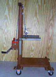
| Freon Bottle Foundry The Cart by Larry Hill - HMSC member In the first two articles I described building the furnace and burner. Here I show the cart which makes the furnace mobile and has an integral lifting device for the furnace top. |
The design: The cart frame is fabricated from square tubing and sits on four casters (the front two swivel). The lifting device is a winch and cable which is described below. The furnace is bolted to the cart for stability. The lift provides enough clearance between the halves of the freon bottle to remove the crucible from the furnace with tongs. The cart is overbuilt because I used materials that I had on hand. Power tools used in construction include a mig welder, drill press, horizontal band saw, and a angle grinder.
 Building
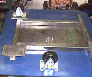
the base: First the base plate
was welded to the frame. The frame is made by welding the 1"
by 1 1/4" square tubing. The tubing extends beyond the base plate far enough
on each side to accommodate the caster mounting plates These plates were drilled for
bolt mounting the casters and welded to the frame bottom.
Building
the base: First the base plate
was welded to the frame. The frame is made by welding the 1"
by 1 1/4" square tubing. The tubing extends beyond the base plate far enough
on each side to accommodate the caster mounting plates These plates were drilled for
bolt mounting the casters and welded to the frame bottom.
Building the handle: The square tubing for the handle was cut to size and welded to the base plate. If you are going to build your own cart, make sure that the handle is tall enough to provide clearance for the crucible to be removed when the furnace top is lifted. The winch plate is welded to the right upright and the winch is bolted to the plate. A U-bolt and block was mounted to the top rail as a cable guide.
Building the lift: Once the handle was finished, the lift was fabricated by welding angle iron which allows the furnace top to slide up and down through rail guides welded to the handle. The lift is attached to winch by a cable, which runs from an eye bolt on the lift to the winch through the block that is attached to the top of the handle.
Finishing off the cart with a paint job: The finished cart was wire brushed to clean off splatter from the mig welder and coated with Ospho as a rust preventative measure. Ospho removes rust from the metal surface and leaves a coat of iron phosphate, which prevents further rusting. The cart was finished off with a Rustoleum for good measure.
Parts List:
1 Ea - winch with cable
1 Ea - pulley block
4 Ea - 3" X 5"
X 1/8" plates to mount castors
4 Ea - castors (2 rigid and 2 swivel)
1
Ea - 12" X 20" X 1/8" plate for cart bottom
2 pieces 16
1/2" long by 1 1/4" square tubing (side rails for base)
2
pieces 17 1/4" long by 1 1/4" square tubing (front and back
rails for base)
2 pieces 32" long by 1 1/2" square tubing
for handle/lift uprights
1 piece 17" long by 1 1/2" square
tubing for handle/lift (handle/crossbar)
1 Pint - Ospho rust killer
1
Can - Rustoleum primer
1 Ea - U-bolt
1 Ea - Eye bolt
16 Ea - 1/4"
X 1" Crown bolts
16 Ea - 1/4" Bolts
32 Ea. - 1/4" Washers
|
The next meeting will be held on Saturday January, 12 2002 at the Collier Library 6200 Pinemont, Houston, TX at 1:00 pm. Bring along a work in progress. Visit Our Web Site |
 |

 Dick
Kostelnicek showed a two piece bed plate that he made from a
one piece plate on his hydraulic press. He said he didn’t
think he would use that brand bed plate again, for some reason.
Dick
Kostelnicek showed a two piece bed plate that he made from a
one piece plate on his hydraulic press. He said he didn’t
think he would use that brand bed plate again, for some reason.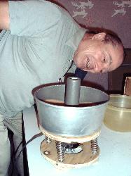 Art
Volz showed several home built and commercial gas burners, a
home made vibrator (parts cleaner, that is!), and a video on one
second operation lathes.
Art
Volz showed several home built and commercial gas burners, a
home made vibrator (parts cleaner, that is!), and a video on one
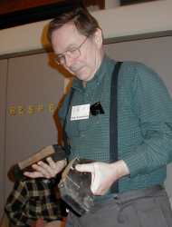
second operation lathes.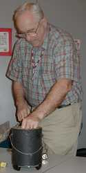 Joe
Williams showed a model hot air engine and lead melting pot
(electric), both of which he built.
Joe
Williams showed a model hot air engine and lead melting pot
(electric), both of which he built.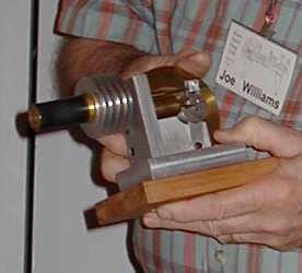
 Joe
Scott showed lathe books from Astragal Press, a hazardous gun
action, and hollow mill and collet closer problems he is experiencing.
Joe
Scott showed lathe books from Astragal Press, a hazardous gun
action, and hollow mill and collet closer problems he is experiencing. Joe
shows how
certain firearms can be converted to automatic fire. Photo not
available.
Joe
shows how
certain firearms can be converted to automatic fire. Photo not
available.