Volume 6, No 11 November, 2001
|
|
Volume 6, No 11 November, 2001 |
|
Treasurer - John Hoff Web Master - Dick Kostelnicek |
Secretary - Ed Gladkowski Editors - David Whittaker, |
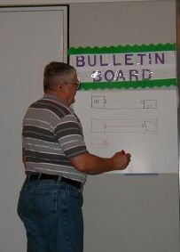 |
Tom Moore gave a very interesting and practical talk on easily aligning a lathe using the simplest equipment. He also gave an explanation of super-accurate centering in the lathe. The full text on the subject will appear in the January, 2002 newsletter. |  |
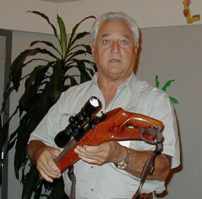
Billy Hobbs showed a custom gun-smithing project.
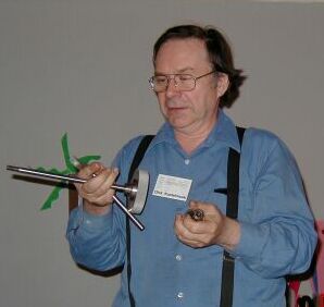
Dick Kostelnicek showed a R-8 to 4c collet adapter he made for
his lathe, complete with drawback and spanner.
|
|
by J. R. (Joe) Williams - member HMSC
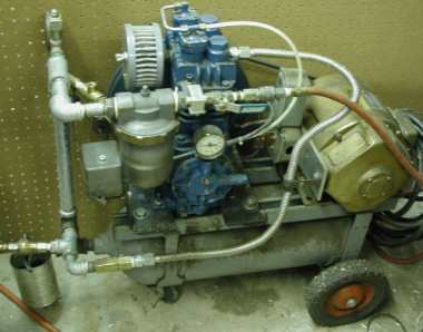
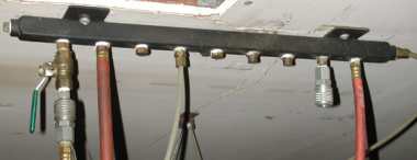
The photos below are of my compressor unit and a ceiling mounted manifold. There is also a tank of about 30 gallon capacity outside the shop in my lawn mower storage area connected with a section of high pressure hydraulic hose. The tank has several quick disconnect fittings and a water draw valve system. The air manifold is a section of light gage steel square tube with a series of tapped holes for 1/4 inch NPT. The end fittings are steel sections welded in place. There is a top connection that goes to an outside tank with a section of high pressure hydraulic hose (low cost surplus material). The supply air from the compressor is via the fitting on the left hand side with the valve.
The air compressor unit is built around an old high pressure steel cylinder for the base with two sections of uni-strut material for the mounting rails. The big wheels are from an old lawn mower The compressor unit started out with an old Ford air conditioning compressor and then was later changed out to the two cylinder Quincy compressor. I increased the motor pulley until the current draw maxed out. The motor is a repulsion start-induction run unit of around 1955 vintage and is rated at 3/4 hp although it is rated at 12 amp (Sears would now rate this at about 5 hp). The compressor is connected to the tank using a section of flexible, corrugated, gas line material. No problems at 125 psig. The outlet air goes to the tank inlet fitting and then up to the outlet side through a coalescer (water trap) and then to a valve and quick-disconnect fitting. At the inlet fitting there is a copper line with an external valve for the water draw. From the valve a copper line goes to the bottom of the tank. I have a 1/4 inch relief valve on the inlet line. The air supply has a filter and could use a silencer. The pressure gage that is on the end of the compressor is the unit's oil pressure indicator. The system's pressure gage is at the top left of the outlet pipe, behind the relief valve, in the photo. The pressure is controlled by a standard compressor pressure switch set for 125 psig maximum and will come back on at about 80 psig. The compressor is equipped with a set of unloader valves, but I am not convinced they work very well. The old repulsion start induction run motor has plenty of starting torque for this service.
The unit needs to be relocated, as it is parked by the side of my surface
grinder (on the clean side) to reduce the shop noise and clear up the space.
Air Compressor |
Air Distribution Manifold |
|
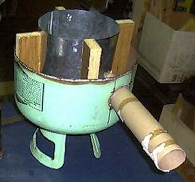
by Larry Hill - member HMSC This is the first of a three-part article about the construction of a small metal melting furnace. Here I cover the design and construction of the furnace. In the remaining parts I'll describe the burner and rest of the foundry. |
 |
 Introduction:
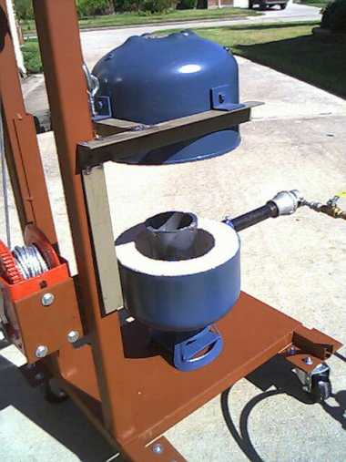
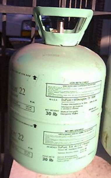
The furnace was designed to use propane as a heat source and a 30# freon
bottle as the shell to hold the refractory. The bottle is 9 in diameter.
The refractory can be pored up to 2 thick, which seems to be adequate
for melting aluminum. Since I plan to melt bronze, it remains to be seen
if 2 of refractory will be enough to get the bronze up to melting temperature.
The furnace, when completed, will hold a crucible about 3 ½ in
diameter and no more than 7 tall. A crucible this small doesnt hold much
aluminum or bronze, but small melts are what this furnace was designed
for. This furnace has melted 15 pounds of aluminum in what I would consider
an acceptable time frame. Using a venturi style burner set at 2-½
p.s.i., the furnace will melt the initial charge of aluminum in less than
15 minutes.
Introduction:
The furnace was designed to use propane as a heat source and a 30# freon
bottle as the shell to hold the refractory. The bottle is 9 in diameter.
The refractory can be pored up to 2 thick, which seems to be adequate
for melting aluminum. Since I plan to melt bronze, it remains to be seen
if 2 of refractory will be enough to get the bronze up to melting temperature.
The furnace, when completed, will hold a crucible about 3 ½ in
diameter and no more than 7 tall. A crucible this small doesnt hold much
aluminum or bronze, but small melts are what this furnace was designed
for. This furnace has melted 15 pounds of aluminum in what I would consider
an acceptable time frame. Using a venturi style burner set at 2-½
p.s.i., the furnace will melt the initial charge of aluminum in less than
15 minutes.
Construction Notes: Construction of the furnace is fairly
straightforward. The bottle is cut, holes are cut, refractory is cast,
and lifting tabs are attached. Painting is optional.
 Cutting
the bottle: The first task is to decide where to cut the freon
bottle in half. Since I wanted the crucible to be lifted out from the side,
I needed enough room to grab the crucible with the tongs from the side.
I figured how much refractory would be in the bottom of the furnace, how
much room was needed for the tuyere, then made sure I had enough of the
crucible exposed to grab it with the tongs. As it turned out, I cut the
bottle in half along the weld line. I used a Drag-gun plasma cutter.
Cutting
the bottle: The first task is to decide where to cut the freon
bottle in half. Since I wanted the crucible to be lifted out from the side,
I needed enough room to grab the crucible with the tongs from the side.
I figured how much refractory would be in the bottom of the furnace, how
much room was needed for the tuyere, then made sure I had enough of the
crucible exposed to grab it with the tongs. As it turned out, I cut the
bottle in half along the weld line. I used a Drag-gun plasma cutter.
Cutting the hole in the top for the exhaust was a piece of cake! I used
the top from a jelly jar as a guide for the plasma cutter. Laying out the
hole for the tuyere was a bit more of a challenge. The cut had to be above
the refractory on the bottom of the furnace and had to line up with the
inside wall. I visually lined up the pipe to the proper angle and marked
the side of the furnace where the tangent of the hole would be. Once I
knew the bottom and side tangents, it was a simple matter to sketch an
oval on bottle where the hole needed to be cut.
 Casting
the refractory: To prepare the bottle for casting the refractory,
I installed wire in the top to help support the refractory. I used sheet
metal to form the inside wall for the refractory. Cardboard tubing was
used to provide the hole for the burner intake. I used about 2/3 of a 75#
bag of 3000 degree castable refractory. Working with refractory is a lot
like working with concrete, except that it requires less water. I mixed
enough to do the top, tamping the refractory in place and making sure that
I didn't leave any voids. I let the refractory set several hours before
removing the sheet metal. I repeated the process to fill the bottom with
refractory. Removing the sheet metal from the bottom
after the refractory was set was a major pain..... I let the top and bottom
set for a couple of days then lit the furnace for a short burn to drive
off any remaining moisture. Not very scientific, but the refractory seems
to be holding up and doing its job.
Casting
the refractory: To prepare the bottle for casting the refractory,
I installed wire in the top to help support the refractory. I used sheet
metal to form the inside wall for the refractory. Cardboard tubing was
used to provide the hole for the burner intake. I used about 2/3 of a 75#
bag of 3000 degree castable refractory. Working with refractory is a lot
like working with concrete, except that it requires less water. I mixed
enough to do the top, tamping the refractory in place and making sure that
I didn't leave any voids. I let the refractory set several hours before
removing the sheet metal. I repeated the process to fill the bottom with
refractory. Removing the sheet metal from the bottom
after the refractory was set was a major pain..... I let the top and bottom
set for a couple of days then lit the furnace for a short burn to drive
off any remaining moisture. Not very scientific, but the refractory seems
to be holding up and doing its job.
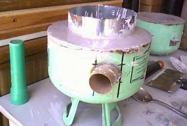
 Installing
the Tuyere: After removing the cardboard tubing, I installed
the 1-¼ pipe that would hold the burner in place. I contoured one
end of the pipe to fit the inside curve of the furnace. The pipe was welded
in place with a mig welder.
Installing
the Tuyere: After removing the cardboard tubing, I installed
the 1-¼ pipe that would hold the burner in place. I contoured one
end of the pipe to fit the inside curve of the furnace. The pipe was welded
in place with a mig welder.
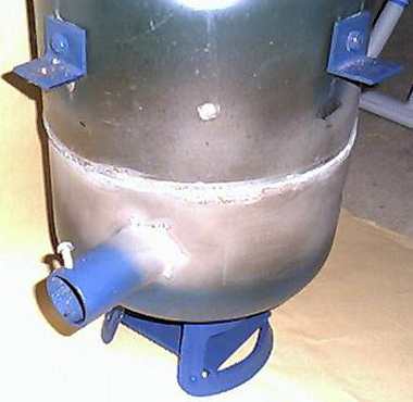
Painting the Furnace: The furnace was finished off with
a paint job. I used 1200-degree engine enamel and didn't prep the surface
except to wipe it down with a clean cloth. The paint has changed color
where the outside of the furnace gets the hottest, but otherwise it seems
to be holding up without peeling.
At this point, the furnace was essentially finished. In the next part
of this article, I'll cover the construction of the burner assembly.
| Dont Forget the Next Meeting !
Regular meetings are held on the second Saturday of the month at the
Collier Library at 6200 Pinemont, Houston, TX. They start at 1:00 PM. The
next one is scheduled for November 10, 2001. Bring along a project
youre been working on.
soon to be.... HomeMetalShopClub.org |
 |
