Volume 8, No 7 - July, 2003
|
|
Volume 8, No 7 - July, 2003 |
|
|
|
|
|
| President - |
Vice President - |
||
| Treasurer - |
Secretary - |
||
| Webmaster - |
Editors - |
||
| Founder - |
SIG Coordinator - |
Statement of Purpose
Membership is open to all those interested in machining metal and tinkering with machines. The club provides a forum for the exchanging of ideas and information. This includes, to a large degree, education in the art of machine tools and practices. Our web site endeavors to bring into the public domain written information that the hobbyist can understand and use. This makes an organization such as this even more important.Regular Meeting
 At
the Collier Library, 6200 Pinemont, Houston, Texas, June
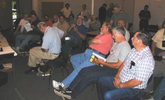
14, 2003, 1:00 pm. Tom Moore, President, presiding. There were 38 persons present,
2 of them visitors: Gene Horr who makes telescopes and Richard Johansonn who
is a semi-retired engineer.
At
the Collier Library, 6200 Pinemont, Houston, Texas, June
14, 2003, 1:00 pm. Tom Moore, President, presiding. There were 38 persons present,
2 of them visitors: Gene Horr who makes telescopes and Richard Johansonn who
is a semi-retired engineer.
At the business meeting, a nominating committee was appointed for upcoming elections. Election of club officers will be at the next regular meeting. Contact Chuck West if you wish to run for a position.
Library books need to be returned! They are due back at next regular meeting following their check out.
Business Meeting
Minutes are sent via email or regular mail to club members.
Presentation
J. D. Wise on the Watchmaker's Lathe

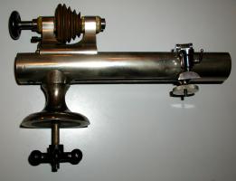
J. D. Wise presented a talk on watch makers lathes and their associated tooling. He showed many excellent slides covering the historical development of these small machines and how they have evolved over several hundred years into the modern precision lathes such as the Hardinge. Various attachments, tools, drives, turrets and work benches were described. Only two makers of this type lathe are still in business. Used lathes can be obtained at reasonable prices since few are training in their use. A very desirable furniture item is the watchmakers roll-top work bench.
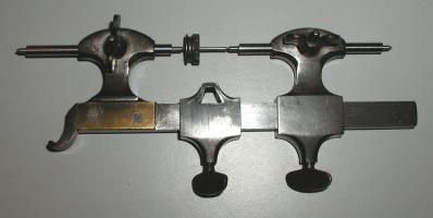
.Show and Tell
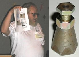
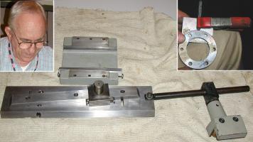
Jim Appleby showed a easy-to-make machinist jack for beginners. See his article below, He also had jack kits for sale. |
Emmett Carstens showed a rake for cleaning buffing wheels. |
John Hoff showed a paint sprayer air dryer using calcium chloride as a descant. |
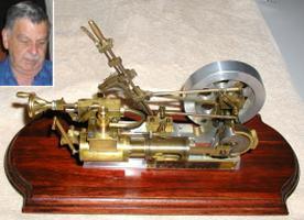
Leo Reed showed a steam engine with reversing valve gear that he built. |
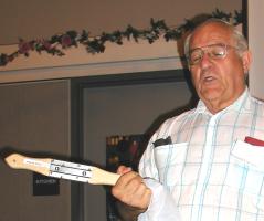
Joe Williams talked about cutting tapers with a taper attachment and tailstock set over. He showed his guide for hand letter stamping around the edge of an object. |
|
|
No activity reported this month.
Computer Numerical Control SIG
No activity reported this month.
Featured Articles
Wagon Wheel Wrench for Miniature Nuts and Bolts
by Ed Gladkowski - HMSC Member
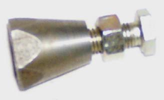
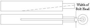
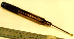 This is an
easily made, light duty wrench for use on model engines or other items using
small hex or square head nuts and bolts. Just cut a slot, sized for the across-flats width of the bolt head, length-wise
partly through the end of a piece of round stock. The slot can be cut with a slitting saw, slotting saw, hacksaw,
or warding file as long as it is a good fit on the nut or bolt. Use drill rod, if you have it, for the round
stock; harden and temper it to about dark straw for durability, or use mild
steel and case-harden it.
This is an
easily made, light duty wrench for use on model engines or other items using
small hex or square head nuts and bolts. Just cut a slot, sized for the across-flats width of the bolt head, length-wise
partly through the end of a piece of round stock. The slot can be cut with a slitting saw, slotting saw, hacksaw,
or warding file as long as it is a good fit on the nut or bolt. Use drill rod, if you have it, for the round
stock; harden and temper it to about dark straw for durability, or use mild
steel and case-harden it.
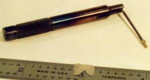
This little wrench can be used on its side like an open-end wrench, or on its end like a nut-driver. As always, be careful and protect your eyes.
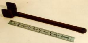
 The pictures show the wrench in use as
both an open-end wrench, and as a nut-driver, on a square-head bolt and nut that is 1/16-in.
across flats. The bolt is #00-90
size. The last picture shows an
original old blacksmith-made wagon wheel axle nut wrench; it fits a nut 1-ľ-in.
across flats.
The pictures show the wrench in use as
both an open-end wrench, and as a nut-driver, on a square-head bolt and nut that is 1/16-in.
across flats. The bolt is #00-90
size. The last picture shows an
original old blacksmith-made wagon wheel axle nut wrench; it fits a nut 1-ľ-in.
across flats.
Ed Note: Prior to submitting this article,
Ed sent in some hex head bolt dimensions, in inches, used in making scale models (see
table below). This information is also available in the Cole's
Power Model catalog.
|
|
Make
Your Own Timing Belt Pulleys
by J. R. Williams - HMSC Member
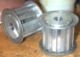
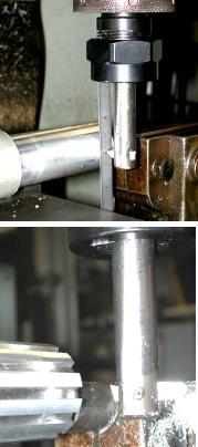 HMSC
member Bill Swann wanted two special timing belt pulleys, wide ones, so he could
use two belts on the same pulley to drive ball screws for a CNC Router he is
fabricating. I suggested we get busy and machine the units. The cutter
was free hand ground from a section of high speed tool bit to match the required
tooth profile and installed in an old boring bar. The aluminum bar stock was
turned to the required diameter and set up in the mill in the dividing head
with the dead center for outboard support. I was able to straddle the
mill's vise with the part. The top photo at the right shows the fly cutter
being set to the center line height by using a machinist's scale, the lower
one with the cutter in operation and the left photo shows the two finished parts
with flanges installed from commercial pulleys.
HMSC
member Bill Swann wanted two special timing belt pulleys, wide ones, so he could
use two belts on the same pulley to drive ball screws for a CNC Router he is
fabricating. I suggested we get busy and machine the units. The cutter
was free hand ground from a section of high speed tool bit to match the required
tooth profile and installed in an old boring bar. The aluminum bar stock was
turned to the required diameter and set up in the mill in the dividing head
with the dead center for outboard support. I was able to straddle the
mill's vise with the part. The top photo at the right shows the fly cutter
being set to the center line height by using a machinist's scale, the lower
one with the cutter in operation and the left photo shows the two finished parts
with flanges installed from commercial pulleys.
Machining
the pulleys was easy compared to the other part of the job-turning down the
ends of two eight foot long, 5/8" diameter ball screws. Bill had annealed
the ends a little and the turning required carbide tooling and several trips
to the grinder. The OD turning was the easy part compared to threading the ends. Another
part of the job was to provide support for the long bar projecting from the
spindle of the lathe. We used a section of 1/2" thin wall electrical conduit
with the ball screw stock inside and supported the combination with a portable
stand. The conduit was clamped to the support stand and held stationary.
Often the new owner of a machine tool, such as a lathe, is hesitant to use the machine because he fears making a mistake, injuring himself, or breaking it. The purpose of this tutorial to show that you can use the lathe to produce a useful object without creating a catastrophe.
The detailed construction
tutorial can be found by clicking
this link or going to the HMSC
Project Page.
Making Piston Rings in Your Shop
by Dick Kostelnicek - HMSC Member
 Recently, I made my first set of CI (cast iron) piston
rings for a stationary model steam engine. From my research on piston
ring fabrication, I’ll briefly describe the four most
popular techniques for making CI rings. Then, I’ll detail how I made mine by
one of the methods.
Recently, I made my first set of CI (cast iron) piston
rings for a stationary model steam engine. From my research on piston
ring fabrication, I’ll briefly describe the four most
popular techniques for making CI rings. Then, I’ll detail how I made mine by
one of the methods.
CI is the material of choice for rings. They may be plated (usually hard chrome) but are mostly used as-is in model engines. The material can be obtained as centrifugally cast round bars ranging from 0.5-in. to over 1-ft. in diameter. It is fully annealed, uniform in grain structure and has no hard spots or slag inclusions. It is a pleasure to machine. The chips are broken pencil lead-like in appearance and size. A chip breaker is not necessary on the lathe’s cutting bit. The resulting chips contain a graphite dust that gets into everything: under machine ways, on the tallest shelves, in your nose, etc - etc. Wear a dust mask and position the suction hose of your shop vacuum near the cutting bit in order to keep down the dust. I’ve tried water based flood coolant to control dust, but you need to clean up immediately, since a wet pile of CI swarf will turn into a tough, rusted, nugget, that sticks tenaciously to any metal or painted machine surface.
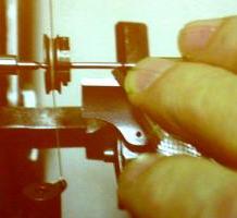
 Ring construction, by any technique
that I'll describe, starts with chucking
up a bar a few inches long and drilling out 95% of the inside. Don’t drill
completely through since the chuck's radial force might warp the resulting
cylinder. I turned a gripper boss on end of the bar in order to chuck
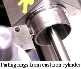
the CI cylinder in a 5C collet held in a square collet block. Then turn and bore to produce a thin CI shell. Use a parting tool that
is as thin as possible to slice off a bunch of rings. Put a bar in the
tailstock protruding
inside the CI shell in order to catch the rings as they drop off. Feed slowly,
just before cut off, so there is minimal thickness of flash to deburr on the
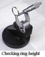
rings inner edge. Deburr the rings on a sheet of kerosene wet garnet paper
supported by an absolutely flat surface plate. Be careful not to remove your
fingerprints as you rub the ring’s side facets in a figure-8 motion. Use this
same technique to size the ring height by a few ten thousands.
Ring construction, by any technique
that I'll describe, starts with chucking
up a bar a few inches long and drilling out 95% of the inside. Don’t drill
completely through since the chuck's radial force might warp the resulting
cylinder. I turned a gripper boss on end of the bar in order to chuck
the CI cylinder in a 5C collet held in a square collet block. Then turn and bore to produce a thin CI shell. Use a parting tool that
is as thin as possible to slice off a bunch of rings. Put a bar in the
tailstock protruding
inside the CI shell in order to catch the rings as they drop off. Feed slowly,
just before cut off, so there is minimal thickness of flash to deburr on the
rings inner edge. Deburr the rings on a sheet of kerosene wet garnet paper
supported by an absolutely flat surface plate. Be careful not to remove your
fingerprints as you rub the ring’s side facets in a figure-8 motion. Use this
same technique to size the ring height by a few ten thousands.
 Next break the ring to form a gap. Some prefer using a
thin hack saw, or just snap it between their fingers, or strike it with a sharp
chisel. Typical proportions are: thickness = 4 percent of bore diameter, height = thickness,
and uncompressed gap = 4 times thickness.
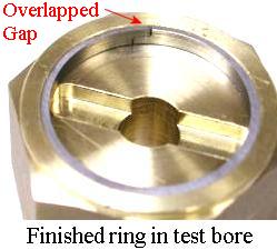
Of course, the compressed gap should be as small as possible. In fact, there may
be some overlap designed into the ring gap ends. For
example; rings made initially oversize can be milled or filed half way through
on each side with an offset in the resulting grooves so that, when compressed,
the two ends overlap. In any case, make extra rings. Remember that more than
one gap per ring is unacceptable.
Next break the ring to form a gap. Some prefer using a
thin hack saw, or just snap it between their fingers, or strike it with a sharp
chisel. Typical proportions are: thickness = 4 percent of bore diameter, height = thickness,
and uncompressed gap = 4 times thickness.
Of course, the compressed gap should be as small as possible. In fact, there may
be some overlap designed into the ring gap ends. For
example; rings made initially oversize can be milled or filed half way through
on each side with an offset in the resulting grooves so that, when compressed,
the two ends overlap. In any case, make extra rings. Remember that more than
one gap per ring is unacceptable.
Here is where the methods differ:
Method One: The cylinder is turned to its final in-place or bore diameter by finishing both inside and outside. After cut-off and gapping, a wedge is inserted into the gap in order to expand the ring’s circumference by 4 times its thickness You can stack a pile of rings and use a single long wedge. Use a containment made from two steel plate end cap held together by a bolt to keep the ring stack stable and exclude the atmospheric oxygen. Cover the outside of the rings with your favorite heat treatment anti-oxidation covering. Soap is the simplest while stainless foil wrap is the most expensive. Heat treat to 1500 degrees F. for 15 minutes or so. Then cool as slowly as possible. This anneals the rings. The expansion will take set and require compression to fit the cylinder bore.
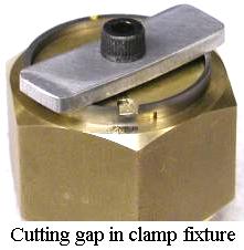
Method Two: Make the rings oversize with an oversize gap. Squeeze the ring till the gap closes, and secure between two flat disc plates held together with a central clamp bolt and nut. Chuck up on the clamp bolt and turn the ring to its bore diameter. The ring will spring back open to its oversize diameter when the face plate clamp is removed.
Method Three: Make the ring to final in-place bore diameter. Don’t gap it yet. Peen the inside of the ring with a hammer. Alternatively, put several layers of masking tape on the entire ring’s surface by wrapping it in a toroidal fashion. Then, use a razor knife to remove the tape from the inside edge. Bead blast the inner exposed CI surface. This will expand the metal along the inner surface. Remove the tape, gap, and you’ll have an expanded ring.
 Method Four: Turn
the outside of the CI cylinder oversize. Offset the cylinder and bore the
inside. The offset should be sufficient so that the ratio of the thickest to
thinnest part the cylinderical shell is about 4:1. Part-off the rings and then file through
at the thinnest section to produce an oversized gap. Don’t turn in reverse order! If
the cylinder’s inside is not right on center when you part-off, you’ll break through
the CI shell and damage the ring before it separates from the CI cylinder.
Method Four: Turn
the outside of the CI cylinder oversize. Offset the cylinder and bore the
inside. The offset should be sufficient so that the ratio of the thickest to
thinnest part the cylinderical shell is about 4:1. Part-off the rings and then file through
at the thinnest section to produce an oversized gap. Don’t turn in reverse order! If
the cylinder’s inside is not right on center when you part-off, you’ll break through
the CI shell and damage the ring before it separates from the CI cylinder.
When uncompressed and when compressed to gap closure, this ring remains circular. And, it will retain its circular shape even as it or the bore wears around evenly. Furthermore, it produces equal pressure at all points around the bore wall. This shape is similar to that of retaining or snap rings. In fact one of the trade names for such rings is “True Arc Rings”. Other objects with varying web thickness that retain their true arc shape when bent are: a leaf spring, and a bow (as in bow and arrow). Because of the variable ring thickness, the ring’s piston should have a close fit to the cylinder bore.
I chose the fourth method to construct my rings because it did not require heat treating, special re-turning clamps, nor sand blasting equipment. My thanks to Ed Gladkowski, HMSC member, for directing me to several articles on piston ring constructiion
References:
Piston Rings,
author unknown, http://www.sylvestris.btinternet.co.uk/rings/rings.htm
Pistons and Rings, author unknown, http://www.5bears.com/pistons.htm
Piston Rings - the Mystery Revieled, by John L. Tulloch,
http://www.oldengine.org/members/holland/images/PistonRings/Thumbnails.html
Piston Rings for your Model Engine, by C. W. Woodson,
Mechanics Illustrated, March 1942.
Heat Treatment
of Piston Rings, by G. Trimble, Model Engineer 17 August 1984.
|
The next meeting will be held on Saturday July 12, 2003 at the Collier Library 6200 Pinemont, Houston, TX at 1:00 p.m. Bring along a work in progress to show. Visit Our Web Site |
 |
Right click below then select [Save
Target As...]
From Netscape select [Save Link As..]
Microsoft
Word version of this newsletter 291 KB


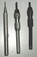
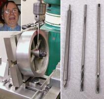 Dick
Kostelnicek showed the tooling that he used to tap a flywheel hub. He
made the countersink extension by Lock Tighting two sizes of
broken (on one end) countersinks bits into opposite ends of a bored out drill rod.
Dick
Kostelnicek showed the tooling that he used to tap a flywheel hub. He
made the countersink extension by Lock Tighting two sizes of
broken (on one end) countersinks bits into opposite ends of a bored out drill rod.