Volume 9, No 3- March, 2004
|
|
Volume 9, No 3- March, 2004 |
|
|
|
|
|
| President - |
Vice President - |
||
| Treasurer - |
Secretary - |
|
|
| Webmaster - |
Editors - |
||
| Founder - |
SIG Coordinators - |
Statement of Purpose
Membership is open to all those interested in machining metal and tinkering with machines. The club provides a forum for the exchanging of ideas and information. This includes, to a large degree, education in the art of machine tools and practices. Our web site endeavors to bring into the public domain written information that the hobbyist can understand and use. This makes an organization such as this even more important.Regular Meeting

 Collier Library, Houston Texas, 1:00 p.m., February
14, 2004, Tom Moore, President presiding. 29 members were present, including one visitor Dan Vernon.
Collier Library, Houston Texas, 1:00 p.m., February
14, 2004, Tom Moore, President presiding. 29 members were present, including one visitor Dan Vernon.
Steve Hall brought his set of tools to sell as he can no longer use them in his trade.
The club secretary resigned. All those
applying for the job, contact the president at the next meeting.
Business Meeting
Minutes are sent via email or regular mail to club members.
Presentation

 Vance
Burns, the club's only admitted blacksmith, gave a slide presentation on the
history and avocational art of blacksmithing. Vance assured us that he
is not a "farrier", one who shoes horses, but a blacksmith. For he
creates articles in iron by the application of hot forging and bending of
iron. He explained the various parts of an anvil as: the horn, or beak -
the tapered end used to form shapes of various radii, the round pritchel hole -
for punching holes, the heel - flat area used in striking and expanding metal,
and the square hardy hole - for holding hardy tools used
in swaging, bending, and cutting . He showed a variety of wrought articles
made by his fellow blacksmiths.
Vance
Burns, the club's only admitted blacksmith, gave a slide presentation on the
history and avocational art of blacksmithing. Vance assured us that he
is not a "farrier", one who shoes horses, but a blacksmith. For he
creates articles in iron by the application of hot forging and bending of
iron. He explained the various parts of an anvil as: the horn, or beak -
the tapered end used to form shapes of various radii, the round pritchel hole -
for punching holes, the heel - flat area used in striking and expanding metal,
and the square hardy hole - for holding hardy tools used
in swaging, bending, and cutting . He showed a variety of wrought articles
made by his fellow blacksmiths.
Show and Tell
Charlies Mynhier ran his 0-10-0 model switcher engine on a internal propane fired steam boiler over a short length of track. |
Gordon Lawson showed photos of the Challenger steam engine's recent visit to Houston TX. See article below. |
Doug Chartier showed some wrenches that he uses to tighten some big collets. |
Dick Kostelnicek showed a miniature nut driver that he uses for model hex head screws. See article below. |
Tom Moore showed his large gas mixer for a gas fired crucible furnace. |
Special Interest Groups Activity
Novice Sig
 Jan Rowland demonstrated the Precision
Fastening and Dowelling Tricks
that was written up in last month's newsletter and answered questions from the
novice group. Joe Williams demonstrated his diamond face wheel tool grinder that sharpens
carbide tools. The drilling demo was repeated, which included several
methods for locating the center of round stock in preparation for center drilling.
Jan Rowland demonstrated the Precision
Fastening and Dowelling Tricks
that was written up in last month's newsletter and answered questions from the
novice group. Joe Williams demonstrated his diamond face wheel tool grinder that sharpens
carbide tools. The drilling demo was repeated, which included several
methods for locating the center of round stock in preparation for center drilling.
Next month, we will have a sharpening workshop. Experienced members,
in addition to novices, are invited to bring tools that need sharpening. Sharpening
topics include: high speed tool bits, off-hand drill sharpening,
cam machine drill sharpening , pocket knife, wood
chisel, axe blade, screw driver, and masonry drills. by Rich Pichler
Comments on last month's articles
We have received some comments on Jan Rowland's article Precision Fastening and Dowelling Tricks
Jan could have mentioned using the top section as a tap guide. Another technique is to use a tubular dowel with the bolt thru the hole and a washer on the outside. by Joe Williams.
 One
thing the author of the dowel pinning article left out was, when welding up an
assembly that was dowel pinned together, it is very important to get everything
absolutely clean. A while ago I had a drive shaft that I wanted to extend a
few inches. I decided that I would use a lathe to drill and ream a hole in both
the extension and the shaft and use a dowel pin to align the two shafts. I pressed
the assembly together and started to weld. Shortly after I had struck an arc
there was a huge explosion. It sounded like a rifle shot. In my haste, I did
not
degrease the pieces as well as I should have and a minute amount of cutting
oil was still in the bottoms of the holes. The oil boiled and when the pressure
got great enough, the assembly blew apart. The shaft about (4-lbs.) sailed
to my right about 50-ft. I never recovered the shaft extension. Since then
I have always put a vent hole in the bottom of such and assembly, or if that
is not
possible I get it very, very clean and make sure that if it was to go "kaboom",
it would not hit me. by William Dodge
One
thing the author of the dowel pinning article left out was, when welding up an
assembly that was dowel pinned together, it is very important to get everything
absolutely clean. A while ago I had a drive shaft that I wanted to extend a
few inches. I decided that I would use a lathe to drill and ream a hole in both
the extension and the shaft and use a dowel pin to align the two shafts. I pressed
the assembly together and started to weld. Shortly after I had struck an arc
there was a huge explosion. It sounded like a rifle shot. In my haste, I did
not
degrease the pieces as well as I should have and a minute amount of cutting
oil was still in the bottoms of the holes. The oil boiled and when the pressure
got great enough, the assembly blew apart. The shaft about (4-lbs.) sailed
to my right about 50-ft. I never recovered the shaft extension. Since then
I have always put a vent hole in the bottom of such and assembly, or if that
is not
possible I get it very, very clean and make sure that if it was to go "kaboom",
it would not hit me. by William Dodge
Featured Articles
Challenger Visit
to Houston, TX
by Gordon Lawson - HMSC Member
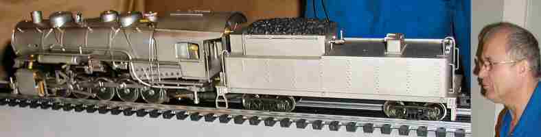
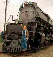
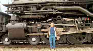
The Union Pacific Challenger, No. 3985, was recently in town for Super Bowl activities. It was located at the intersection of Holly Hall and Almeda streets in Houston, TX..
Union Pacific built 105 Challenger steam engines between 1936 and 1943. No. 3985, the one in accompanying photos was built in July, 1943, by the American Locomotive Company (ALCO) at their Schenectady Works plant. It is the largest operating steam locomotive in the world today. On its way to and from events, like the Super Bowl, it hauls freight, so it does "pay it's way". The 3985 last operated in regular train service in 1957. It was officially retired in 1962 and was stored in Cheyenne, Wyoming, and was placed on display in 1975 near the Cheyenne depot. A group of Union Pacific employee volunteers restored the locomotive to running condition in 1981. It was converted to run on fuel oil in 1990.
The specifications:
Wheel arrangement: 4-6-6-4
Weight: 1,070,000 pounds
Height:
About 17 feet.
Length: About 122 feet.
Steam pressure:
4 X 21-in cylinders @ 280 psig to power twelve 69-in dia. driving wheels
developing 97,350 pounds of tractive force
Firebox: 132 square
ft.
Articulation: The frame of the locomotive is hinged ahead
of the rear cylinders which allows the engine to follow curves easily.
Tender:
The tender is called a "caterpillar", based on its appearance.
It has 14 wheels. It holds 25,000 gallons of water and 5945
gallons of No. 5 fuel oil. Originally, it had a tender that carried
32-tons of coal.
Top speed: 70 Miles per hour.

Controlling hole depth when
using the lathe tailstock
by John Hoff - HMSC Member
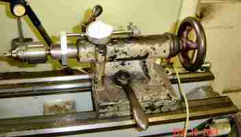 I needed to
drill a blind hole in a number of pieces to a precise depth of 0.200-in. Counting
the number of turns or fraction of turns on the lathe tailstock wheel just
wouldn�t be accurate enough. To solve my problem, I�ve mounted a 1-in. travel
dial on my lathe tailstock.
I needed to
drill a blind hole in a number of pieces to a precise depth of 0.200-in. Counting
the number of turns or fraction of turns on the lathe tailstock wheel just
wouldn�t be accurate enough. To solve my problem, I�ve mounted a 1-in. travel
dial on my lathe tailstock.
The travel dial is mounted with the measuring pin facing in the direction of the tailstock wheel. A clamp is attached to the tailstock spindle capable of holding a rigid rod extending above the tailstock casting and back toward the tailstock's wheel. A metal arm with a thumb screw adjustment slips over the rod and contacts the travel dial shaft.
Now, whenever I need precise drilling, I advance the drill point until it just
touches the work, move the arm along the
rod until it contacts the travel dial, tighten the thumb screw, set the dial to
zero and drill away.
Mill/Drill and Drill Press Alignment during Tool Changes
by Ed Gladkowski - HMSC Member
When performing multiple operations on the same work piece, while using a drill press or mill/drill with a round column instead of a dovetailed column, a problem arises when changing from short to long tooling, especially if the machine has limited quill travel. If the machine spindle has to be brought close to the work for, say, a center drill, there is often insufficient room to change to a long drill or reamer without swinging, or raising the machine head, or swinging or lowering the drill press table. There have been some elaborate �fixes� to retain alignment in this situation, especially for mill/drills, for example, milling keyways the whole length of the round column with keys in the machine head to match; or mounting a laser pointer on the head targeted on a vertical line marked on the shop wall.
A quick and simple method I�ve had good luck with is as follows:
(1) If the head (or table) of the machine only has to be swung sideways to change a tool, mount a magnetic-base indicator on the work, vise or table with the indicator point zeroed against any solid point on the head. Unclamp the head or table, swing it far enough to change the tool, then swing it back and re-clamp it at the original zero indicator reading.
(2) If
the machine head has to be raised (or the table lowered), attach the
indicator to the machine's head magnetically or in the chuck or collet. Clamp a parallel vertically to the work, or
to an angle plate or in a vise on the table. The parallel needs to be a little taller than the amount you need
to raise or lower the machine�s head or table.
Zero the indicator against the edge of the parallel, unclamp the head or
table, and move it up or down. Then, re-clamp
it at the same zero indicator reading, at its new position along the length of
the parallel.
Cutting Oil Cup
by J. R. Williams - HMSC Member
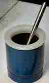 A necessity in the shop is a small cup holding cutting
oil and a brush. I have used many
different containers and today, as I was cleaning up the shop, an empty
disposable propane cylinder was about to be tossed when I decided the bottom
three inches of the cylinder would make a good cutting oil container. Furthermore,
it had a good flat base. A quick pass
thru the cut-off bandsaw, with coolant on, resulted in the container. (Caution - be
sure the cylinder is empty before cutting!). A plastic
top rim section ( 1/2" thick ) was
turned from a section of High Density Polyethelene and pressed in to the top of the cut
off section. The slightly extended rim
makes it easy to handle.
A necessity in the shop is a small cup holding cutting
oil and a brush. I have used many
different containers and today, as I was cleaning up the shop, an empty
disposable propane cylinder was about to be tossed when I decided the bottom
three inches of the cylinder would make a good cutting oil container. Furthermore,
it had a good flat base. A quick pass
thru the cut-off bandsaw, with coolant on, resulted in the container. (Caution - be
sure the cylinder is empty before cutting!). A plastic
top rim section ( 1/2" thick ) was
turned from a section of High Density Polyethelene and pressed in to the top of the cut
off section. The slightly extended rim
makes it easy to handle.
Work Support
-
Milling Machine
by J. R. Williams - HMSC Member
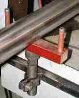
 The left
hand photo shows a
work support that I fabricated to support long work held in my milling machine's vise.
This job was to mill a short slot in the end of an 8 ft. section of
1-1/2-in. SS ( stainless steel ) pipe. There was
no
problem holding the work in the vise but the length of the work made it almost
impossible to support the work and keep it level and close the vise. I have stacked up parallels and used wedges
in the past but that was not satisfactory. The support is built around a 3/4-in. socket head cap screw with a
hole drilled and tapped in the end for a 5/16-in. flat head screw to hold the
linen filled phenolic material on the end of the large screw. The ends have 1/4-in. socket head cap
screws with copper tube sleeves. The
phenolic material and copper tube sleeves were used to prevent any marking of
the work. The large nut has two tabs
welded on to provide the clamp action after the nut was split with a saw. The nut is welded to a section of 3/4-in.
square tube material that is bolted to the outside of the mill's splash shield. The position allows the slide-in shield section to be replaced
and does not interfere with the table slots.
The left
hand photo shows a
work support that I fabricated to support long work held in my milling machine's vise.
This job was to mill a short slot in the end of an 8 ft. section of
1-1/2-in. SS ( stainless steel ) pipe. There was
no
problem holding the work in the vise but the length of the work made it almost
impossible to support the work and keep it level and close the vise. I have stacked up parallels and used wedges
in the past but that was not satisfactory. The support is built around a 3/4-in. socket head cap screw with a
hole drilled and tapped in the end for a 5/16-in. flat head screw to hold the
linen filled phenolic material on the end of the large screw. The ends have 1/4-in. socket head cap
screws with copper tube sleeves. The
phenolic material and copper tube sleeves were used to prevent any marking of
the work. The large nut has two tabs
welded on to provide the clamp action after the nut was split with a saw. The nut is welded to a section of 3/4-in.
square tube material that is bolted to the outside of the mill's splash shield. The position allows the slide-in shield section to be replaced
and does not interfere with the table slots.
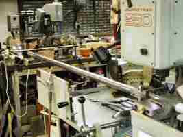
In the right photo, notice the use of my work stop unit that is over the tube near the vise to prevent the work tube dropping down when the vise is loose. Having the support at the correct height has been a big help. The height was set by using a long straight edge clamped in the vise and the work support adjusted up to touch the straight edge's blade. As you can see, space is a premium in my shop, especially with long work. To assemble a welding torch, that uses the 8-ft. SS tube, I have to slide parts together coming into the shop thru the outside door.
Make Your
Own Hex Drivers
by Dick Kostelnicek
- HMSC Member
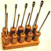
 Recently
I made a set of hex nut-&-bolt drivers, sometimes called "spintights", for
model hex head screws. These screws mimic to scale large full size bolts
and are generally taller in head height than conventional miniature
hex head screws. Furthermore, the hex sizes (distance across the flats) are
sometimes not available in common spintights. Also, commercially made spintights have
a thick socket wall and short-thick shank, making them all but useless
in getting into tight places on engineering models. I made a set of ten drivers
ranging from #0-80 (3/32-in across flat) to #12-24 (5/16 across flat). Each
has a 1-ft long 3/16-in. diameter driver shank. The socket wall thickness
is a mere 0.045-in. The wood handles are made from a discarded broom handle.
Recently
I made a set of hex nut-&-bolt drivers, sometimes called "spintights", for
model hex head screws. These screws mimic to scale large full size bolts
and are generally taller in head height than conventional miniature
hex head screws. Furthermore, the hex sizes (distance across the flats) are
sometimes not available in common spintights. Also, commercially made spintights have
a thick socket wall and short-thick shank, making them all but useless
in getting into tight places on engineering models. I made a set of ten drivers
ranging from #0-80 (3/32-in across flat) to #12-24 (5/16 across flat). Each
has a 1-ft long 3/16-in. diameter driver shank. The socket wall thickness
is a mere 0.045-in. The wood handles are made from a discarded broom handle.
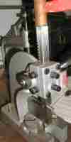
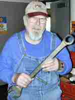
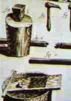
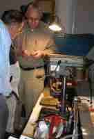
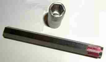
 The
socket, with inserted anvil, is then struck on all six sides near the socket's
open end with a hammer in order to cold forge the socket around the anvil. This
process also loosens the anvil from the socket's hex cavity, thereby giving
sufficient socket clearance for the required hex size. Rather than use a hammer,
with the possibility of hitting a finger, I employed a small arbor press
and steel block to compress the socket against the flats of the hex anvil. The
photo at the left shows me striking the arbor press ram with a copper hammer,
which nicely cold forged two sides of the socket in one operation.
The
socket, with inserted anvil, is then struck on all six sides near the socket's
open end with a hammer in order to cold forge the socket around the anvil. This
process also loosens the anvil from the socket's hex cavity, thereby giving
sufficient socket clearance for the required hex size. Rather than use a hammer,
with the possibility of hitting a finger, I employed a small arbor press
and steel block to compress the socket against the flats of the hex anvil. The
photo at the left shows me striking the arbor press ram with a copper hammer,
which nicely cold forged two sides of the socket in one operation.
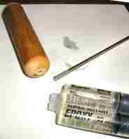
The sockets were drilled through for a 3/16-in. shank that was fastened with silver solder. The opposite end of the shank was knurled and fastened with epoxy into a short drilled section of broom handle. After the silver soldering, I annealed the sockets, since they were made from water hardening drill rod, by allowing them to cool very slowly while submerged in powered line. If not annealed, they will crack under high torque due to the thin socket wall thickness.
|
Visit Our Home Page at |
 |
Right click below then select [Save
Target As...]
From Netscape select [Save Link As..]
Microsoft
Word version of this newsletter 195 KB